How to Use tof: Examples, Pinouts, and Specs
Introduction
Time-of-Flight (ToF) sensors are advanced distance measurement devices that operate by emitting a light signal (typically infrared) and calculating the time it takes for the signal to reflect off an object and return to the sensor. This precise measurement enables accurate distance and depth sensing, making ToF sensors a popular choice in a wide range of applications.
Explore Projects Built with tof
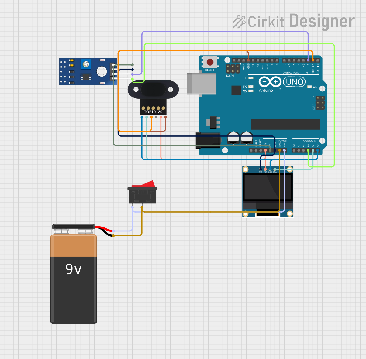


Explore Projects Built with tof
Common Applications and Use Cases
- Robotics: Obstacle detection and navigation.
- Smartphones: Gesture recognition and augmented reality (AR).
- Industrial Automation: Proximity sensing and object detection.
- Automotive: Advanced driver-assistance systems (ADAS) and parking sensors.
- Consumer Electronics: Presence detection and touchless control interfaces.
Technical Specifications
Below are the general technical specifications for a typical ToF sensor (e.g., VL53L0X or similar models). Always refer to the datasheet of your specific sensor for exact details.
| Parameter | Value |
|---|---|
| Operating Voltage | 2.6V to 3.5V |
| Communication Interface | I2C |
| Measurement Range | Up to 2 meters (varies by model) |
| Accuracy | ±3% (depending on conditions) |
| Field of View (FoV) | ~25° |
| Operating Temperature | -20°C to 70°C |
| Power Consumption | ~20mW (active mode) |
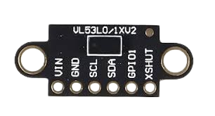
Pin Configuration and Descriptions
The following table describes the typical pinout for a ToF sensor module:
| Pin Name | Description |
|---|---|
| VCC | Power supply input (2.6V to 3.5V). |
| GND | Ground connection. |
| SDA | I2C data line for communication with the host. |
| SCL | I2C clock line for communication with the host. |
| XSHUT | Shutdown pin (active low, optional). |
| GPIO1 | Interrupt output (optional, configurable). |
Usage Instructions
How to Use the Component in a Circuit
- Power Supply: Connect the VCC pin to a 3.3V power source and the GND pin to ground.
- I2C Communication: Connect the SDA and SCL pins to the corresponding I2C pins on your microcontroller (e.g., Arduino UNO: A4 for SDA, A5 for SCL).
- Optional Pins:
- Use the XSHUT pin to enable or disable the sensor programmatically.
- Configure the GPIO1 pin for interrupt-based applications if needed.
- Pull-Up Resistors: Ensure that the SDA and SCL lines have appropriate pull-up resistors (typically 4.7kΩ).
Important Considerations and Best Practices
- Ambient Light: Excessive ambient light can interfere with the sensor's performance. Use the sensor in controlled lighting conditions or shield it from direct sunlight.
- Reflective Surfaces: Highly reflective or transparent surfaces may cause inaccurate readings. Test the sensor in your specific environment.
- I2C Address: Some ToF sensors allow changing the default I2C address. This is useful when using multiple sensors on the same bus.
- Mounting: Ensure the sensor is mounted securely and aligned properly for accurate measurements.
Example Code for Arduino UNO
Below is an example of how to use a ToF sensor (e.g., VL53L0X) with an Arduino UNO:
#include <Wire.h>
#include <Adafruit_VL53L0X.h>

// Create an instance of the VL53L0X sensor
Adafruit_VL53L0X lox = Adafruit_VL53L0X();

void setup() {
  Serial.begin(9600); // Initialize serial communication
  while (!Serial) {
    delay(10); // Wait for the serial port to connect
  }

  Serial.println("Initializing ToF Sensor...");

  // Initialize the sensor
  if (!lox.begin()) {
    Serial.println("Failed to initialize VL53L0X! Check wiring.");
    while (1); // Halt execution if initialization fails
  }

  Serial.println("VL53L0X Initialized Successfully.");
}

void loop() {
  VL53L0X_RangingMeasurementData_t measure;

  // Perform a ranging measurement
  lox.rangingTest(&measure, false);

  // Check if the measurement is valid
  if (measure.RangeStatus != 4) { // 4 indicates an out-of-range error
    Serial.print("Distance (mm): ");
    Serial.println(measure.RangeMilliMeter);
  } else {
    Serial.println("Out of range");
  }

  delay(100); // Wait before the next measurement
}
Troubleshooting and FAQs
Common Issues and Solutions
Sensor Not Detected on I2C Bus:
- Cause: Incorrect wiring or I2C address mismatch.
- Solution: Verify the SDA and SCL connections. Check the sensor's I2C address using an I2C scanner sketch.
Inaccurate Distance Measurements:
- Cause: Reflective or transparent surfaces, or excessive ambient light.
- Solution: Test the sensor in a controlled environment and avoid reflective surfaces.
Sensor Fails to Initialize:
- Cause: Insufficient power supply or incorrect wiring.
- Solution: Ensure the VCC pin is receiving 3.3V and all connections are secure.
Out-of-Range Errors:
- Cause: Object is too close or too far from the sensor.
- Solution: Ensure the object is within the sensor's specified measurement range.
FAQs
Q: Can I use multiple ToF sensors on the same I2C bus?
A: Yes, but you must assign unique I2C addresses to each sensor. Refer to the sensor's datasheet for instructions on changing the address.Q: What is the maximum range of a ToF sensor?
A: The range varies by model, but most consumer-grade ToF sensors can measure up to 2 meters.Q: Can ToF sensors detect transparent objects?
A: ToF sensors may struggle with transparent objects due to insufficient reflection of the light signal.Q: Is it possible to use a ToF sensor outdoors?
A: Yes, but performance may degrade in direct sunlight. Consider using an optical filter or shading the sensor.
This concludes the documentation for the Time-of-Flight (ToF) sensor. For further details, consult the datasheet of your specific sensor model.