How to Use OLED Estufa: Examples, Pinouts, and Specs
Introduction
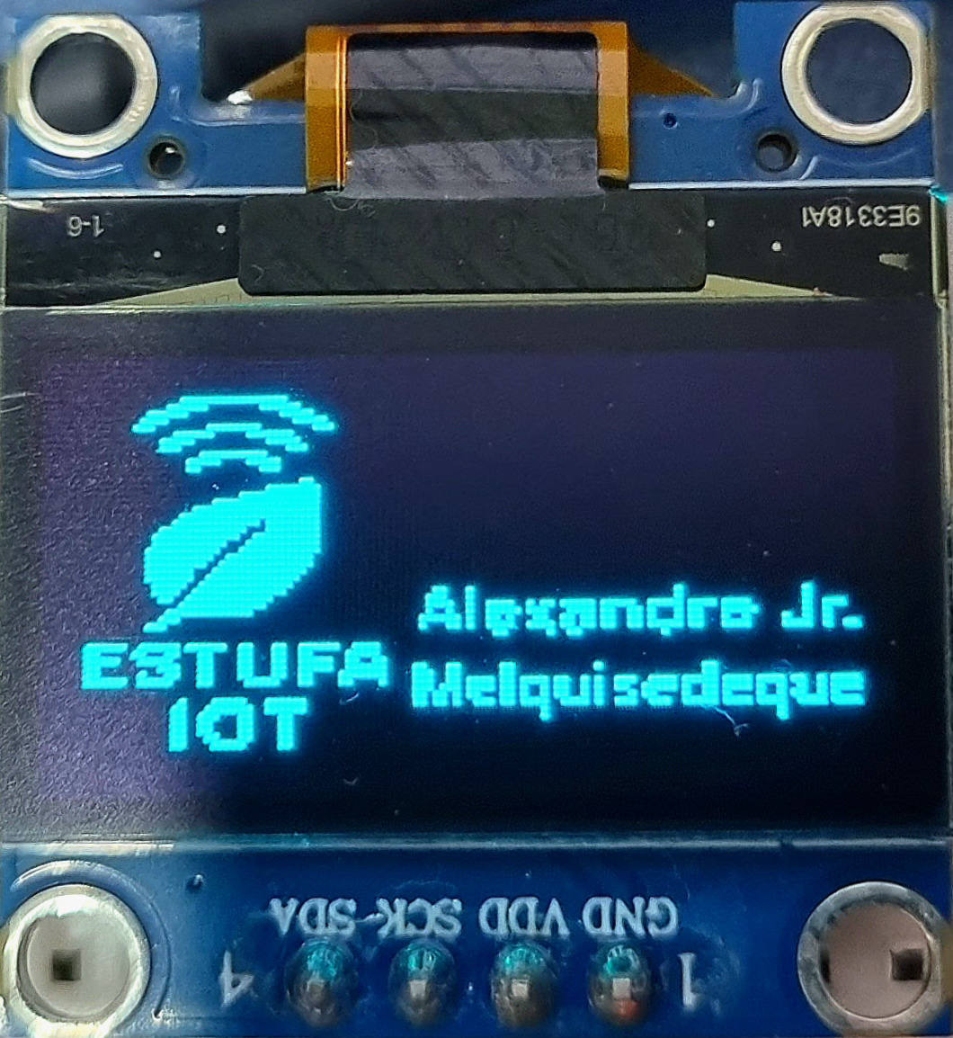
The OLED Estufa, based on the SSD1306 driver, is a compact and energy-efficient display module manufactured in China. It features a monochrome OLED screen that provides high contrast and sharp visuals, making it ideal for displaying text, graphics, and simple animations. The OLED Estufa is widely used in embedded systems, IoT devices, and DIY electronics projects due to its low power consumption and compatibility with popular microcontrollers like Arduino and Raspberry Pi.
Explore Projects Built with OLED Estufa
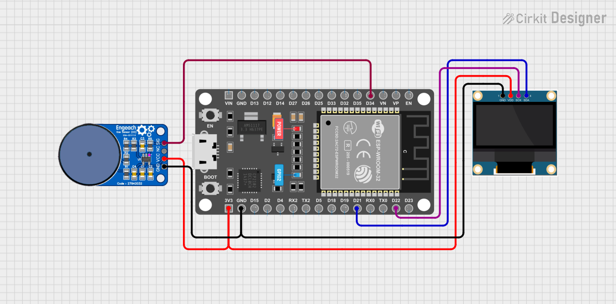
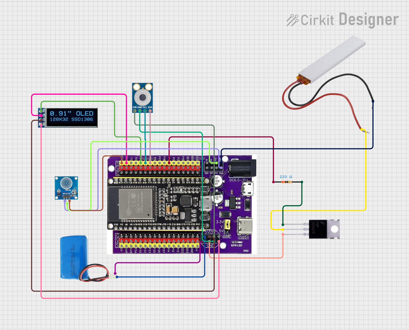

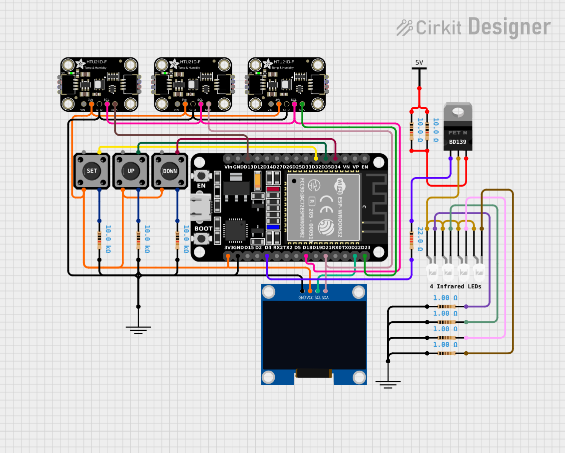
Explore Projects Built with OLED Estufa
Common Applications and Use Cases
- Displaying sensor data in IoT projects
- User interfaces for embedded systems
- Wearable devices
- Home automation displays
- Debugging and monitoring tools for microcontroller projects
Technical Specifications
The OLED Estufa is powered by the SSD1306 driver and comes with the following technical specifications:
| Parameter | Value |
|---|---|
| Display Type | Monochrome OLED |
| Resolution | 128 x 64 pixels |
| Driver IC | SSD1306 |
| Interface | I2C (default) or SPI |
| Operating Voltage | 3.3V to 5V |
| Current Consumption | ~20mA (typical) |
| Viewing Angle | >160° |
| Operating Temperature | -40°C to +85°C |
| Dimensions | 27mm x 27mm x 4mm |
Pin Configuration and Descriptions
The OLED Estufa module typically uses a 4-pin I2C interface. Below is the pinout:
| Pin | Name | Description |
|---|---|---|
| 1 | GND | Ground connection |
| 2 | VCC | Power supply (3.3V or 5V) |
| 3 | SCL | Serial Clock Line for I2C communication |
| 4 | SDA | Serial Data Line for I2C communication |
For SPI communication, additional pins (CS, DC, and RES) may be present, depending on the module variant.
Usage Instructions
How to Use the Component in a Circuit
- Power the Module: Connect the
VCCpin to a 3.3V or 5V power source and theGNDpin to ground. - Connect I2C Lines: Connect the
SCLandSDApins to the corresponding I2C pins on your microcontroller. For Arduino UNO:SCLconnects to A5.SDAconnects to A4.
- Install Required Libraries: Use the Adafruit SSD1306 and Adafruit GFX libraries for Arduino to simplify programming.
- Write Code: Use the example code below to initialize and display content on the OLED.
Important Considerations and Best Practices
- Ensure the I2C address of the OLED module matches the address in your code. The default address is typically
0x3C. - Use pull-up resistors (4.7kΩ to 10kΩ) on the
SCLandSDAlines if not already present on the module. - Avoid exposing the module to voltages higher than 5V to prevent damage.
- Handle the module carefully to avoid damaging the OLED screen.
Example Code for Arduino UNO
#include <Wire.h>
#include <Adafruit_GFX.h>
#include <Adafruit_SSD1306.h>

// Define OLED display width and height
#define SCREEN_WIDTH 128
#define SCREEN_HEIGHT 64

// Create an SSD1306 display object
Adafruit_SSD1306 display(SCREEN_WIDTH, SCREEN_HEIGHT, &Wire, -1);

void setup() {
  // Initialize serial communication for debugging
  Serial.begin(9600);

  // Initialize the OLED display
  if (!display.begin(SSD1306_I2C_ADDRESS, 0x3C)) {
    Serial.println(F("SSD1306 allocation failed"));
    for (;;); // Halt execution if initialization fails
  }

  // Clear the display buffer
  display.clearDisplay();

  // Display a welcome message
  display.setTextSize(1); // Set text size to 1
  display.setTextColor(SSD1306_WHITE); // Set text color to white
  display.setCursor(0, 0); // Set cursor to top-left corner
  display.println(F("Hello, OLED Estufa!"));
  display.display(); // Render the text on the screen
  delay(2000); // Wait for 2 seconds
}

void loop() {
  // Example: Display a counter
  static int counter = 0;

  // Clear the display buffer
  display.clearDisplay();

  // Display the counter value
  display.setCursor(0, 0);
  display.print(F("Counter: "));
  display.println(counter);

  // Render the updated content
  display.display();

  // Increment the counter and wait
  counter++;
  delay(1000);
}
Troubleshooting and FAQs
Common Issues and Solutions
Display Not Turning On
- Cause: Incorrect wiring or insufficient power supply.
- Solution: Double-check the connections and ensure the power supply is stable.
No Output on the Screen
- Cause: Incorrect I2C address or uninitialized display.
- Solution: Verify the I2C address (default is
0x3C) and ensure thedisplay.begin()function is called in the setup.
Flickering or Unstable Display
- Cause: Noise on the I2C lines or insufficient pull-up resistors.
- Solution: Add or replace pull-up resistors on the
SCLandSDAlines.
Partial or Distorted Display
- Cause: Damaged OLED screen or incorrect resolution settings.
- Solution: Verify the resolution settings in the code and inspect the screen for physical damage.
FAQs
Can I use the OLED Estufa with a 3.3V microcontroller? Yes, the module is compatible with both 3.3V and 5V systems.
What is the maximum I2C speed supported? The SSD1306 driver supports I2C speeds up to 400kHz.
Can I use this module with Raspberry Pi? Yes, the OLED Estufa is fully compatible with Raspberry Pi. Use the
smbuslibrary in Python for I2C communication.How do I change the I2C address? Some modules have solder pads or jumpers to change the I2C address. Refer to the module's datasheet for details.