How to Use GPS: Examples, Pinouts, and Specs
Introduction
A Global Positioning System (GPS) receiver determines the precise location of an object on Earth using signals from satellites. It calculates latitude, longitude, altitude, and time by analyzing data from multiple satellites in orbit. GPS modules are widely used in navigation systems, tracking devices, drones, and IoT applications. They are essential for applications requiring real-time location data.
Common applications and use cases:
- Vehicle navigation and fleet management
- Personal tracking devices
- Autonomous drones and robots
- Geotagging in photography
- Outdoor sports and fitness tracking
- IoT devices requiring location-based services
Explore Projects Built with GPS


Explore Projects Built with GPS
Technical Specifications
Below are the general technical specifications for a typical GPS module (e.g., NEO-6M GPS module):
| Parameter | Specification |
|---|---|
| Operating Voltage | 3.3V to 5V |
| Operating Current | 20mA to 30mA |
| Communication Protocol | UART (Serial) |
| Baud Rate | Default: 9600 bps (configurable) |
| Position Accuracy | 2.5 meters CEP (Circular Error Probable) |
| Time to First Fix (TTFF) | Cold Start: 27s, Hot Start: 1s |
| Antenna Type | External active or passive antenna |
| Operating Temperature | -40°C to +85°C |
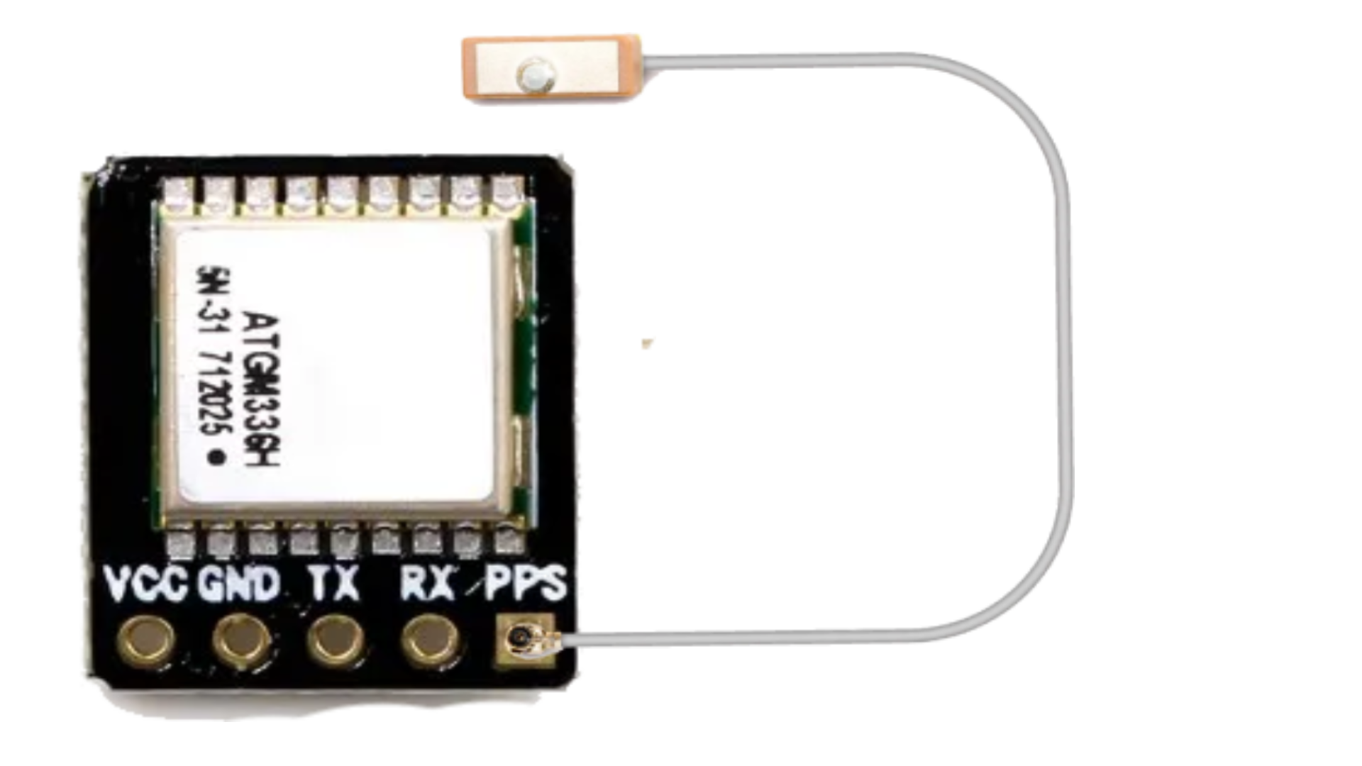
Pin Configuration
The pinout for a typical GPS module is as follows:
| Pin Name | Description |
|---|---|
| VCC | Power supply input (3.3V to 5V) |
| GND | Ground |
| TX | Transmit data (connect to RX of microcontroller) |
| RX | Receive data (connect to TX of microcontroller) |
| PPS | Pulse per second output (optional, for timing applications) |
Usage Instructions
How to Use the GPS Module in a Circuit
- Power the Module: Connect the VCC pin to a 3.3V or 5V power source and the GND pin to ground.
- Connect to a Microcontroller: Use the TX and RX pins to establish a serial communication link with a microcontroller (e.g., Arduino UNO). Ensure the baud rate matches the module's default (typically 9600 bps).
- Antenna Placement: Attach an external antenna to the GPS module. For optimal performance, place the antenna in an open area with a clear view of the sky.
- Read GPS Data: Use the microcontroller to read and parse NMEA (National Marine Electronics Association) sentences, which contain location and time data.
Important Considerations and Best Practices
- Clear Sky View: GPS modules require a clear line of sight to satellites. Avoid using them indoors or in areas with heavy obstructions.
- Cold Start vs. Hot Start: A cold start (first-time use) may take longer to acquire satellite signals. Subsequent uses (hot starts) will be faster.
- Power Supply: Ensure a stable power supply to avoid data corruption or loss of signal.
- Signal Interference: Keep the GPS module away from sources of electromagnetic interference, such as motors or high-frequency circuits.
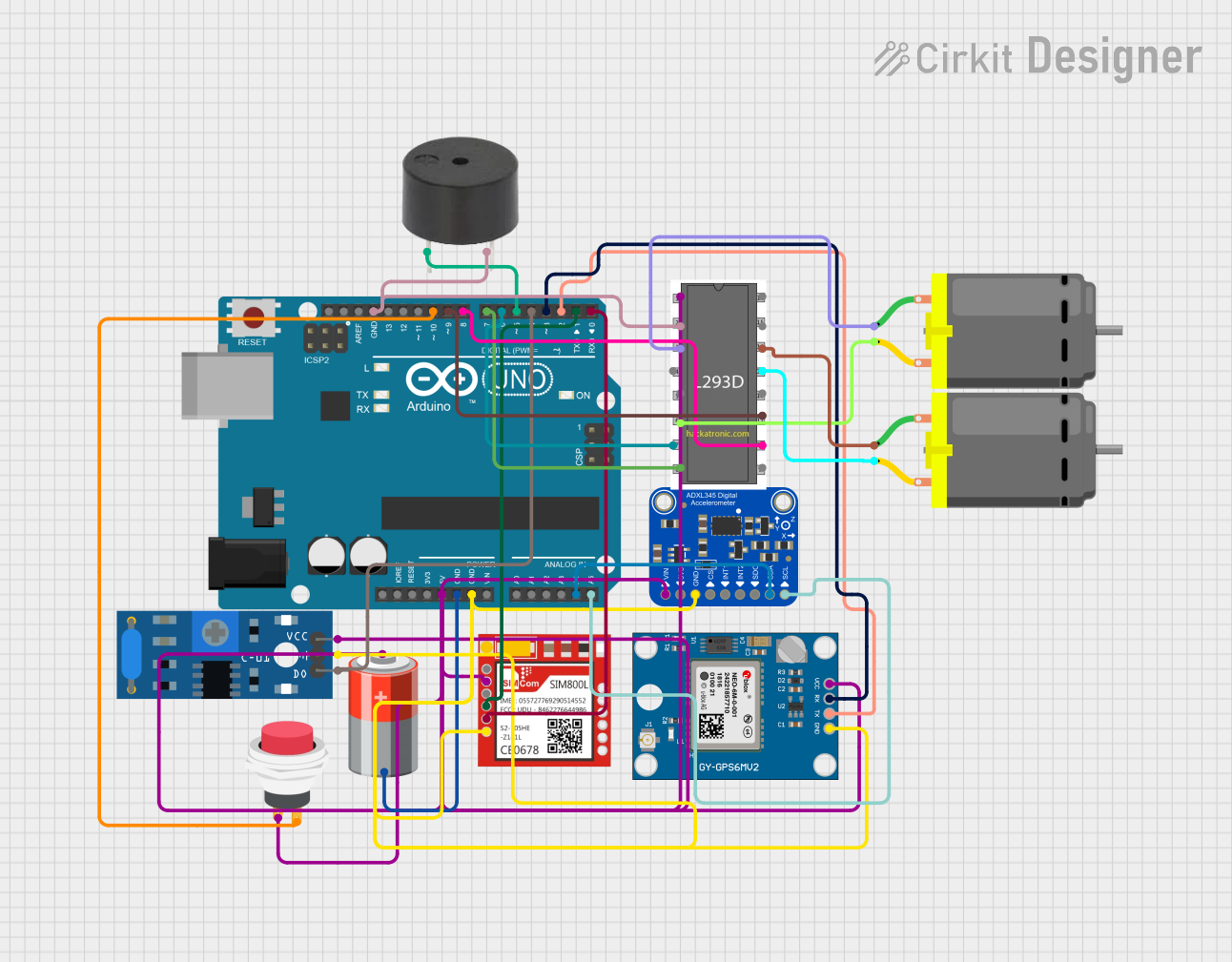
Example: Connecting GPS to Arduino UNO
Below is an example of how to connect and use a GPS module with an Arduino UNO:
Circuit Connections
- GPS VCC → Arduino 5V
- GPS GND → Arduino GND
- GPS TX → Arduino Digital Pin 4 (via SoftwareSerial)
- GPS RX → Arduino Digital Pin 3 (via SoftwareSerial)
Arduino Code
#include <SoftwareSerial.h>

// Define RX and TX pins for SoftwareSerial
SoftwareSerial gpsSerial(4, 3); // RX = Pin 4, TX = Pin 3

void setup() {
  Serial.begin(9600); // Initialize Serial Monitor at 9600 bps
  gpsSerial.begin(9600); // Initialize GPS module at 9600 bps
  Serial.println("GPS Module Initialized");
}

void loop() {
  // Check if data is available from the GPS module
  while (gpsSerial.available()) {
    char c = gpsSerial.read(); // Read one character from GPS
    Serial.print(c); // Print the character to Serial Monitor
  }
}
Notes:
- Use a GPS parsing library (e.g., TinyGPS++) for easier extraction of latitude, longitude, and other data.
- Ensure the baud rate in the code matches the GPS module's default baud rate.
Troubleshooting and FAQs
Common Issues and Solutions
No GPS Data Received
- Cause: Incorrect wiring or baud rate mismatch.
- Solution: Double-check the connections and ensure the baud rate in the code matches the GPS module's default.
Long Time to Acquire Signal
- Cause: Poor antenna placement or obstructions.
- Solution: Place the antenna in an open area with a clear view of the sky.
Unstable or Corrupted Data
- Cause: Power supply issues or electromagnetic interference.
- Solution: Use a stable power source and keep the module away from interference sources.
GPS Module Not Responding
- Cause: Damaged module or incorrect voltage.
- Solution: Verify the module's operating voltage and replace it if necessary.
FAQs
Q: Can I use the GPS module indoors?
- A: GPS modules perform poorly indoors due to limited satellite visibility. Use them in open areas for best results.
Q: How do I improve GPS accuracy?
- A: Use an active antenna and ensure a clear view of the sky. Avoid areas with tall buildings or dense foliage.
Q: What is the purpose of the PPS pin?
- A: The PPS (Pulse Per Second) pin provides a precise timing signal, useful for time synchronization in advanced applications.
Q: Can I change the baud rate of the GPS module?
- A: Yes, most GPS modules allow baud rate configuration via specific commands. Refer to the module's datasheet for details.