How to Use Amplifier: Examples, Pinouts, and Specs
Introduction
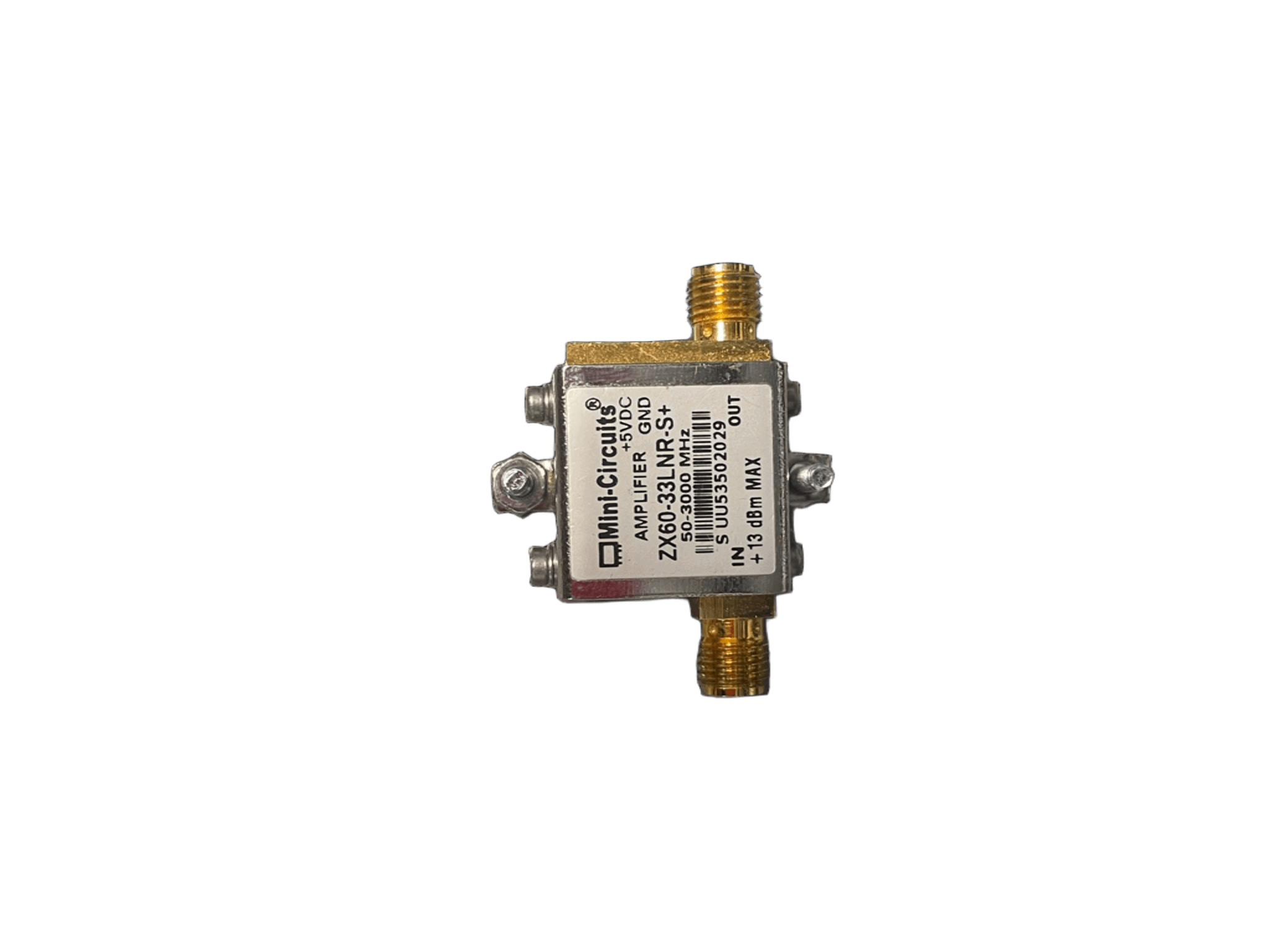
An amplifier is an electronic device designed to increase the power, voltage, or current of an input signal. It is a fundamental component in electronics, widely used in applications such as audio systems, radio transmission, instrumentation, and communication systems. Amplifiers are essential for enhancing weak signals to levels suitable for further processing or output.
Common applications of amplifiers include:
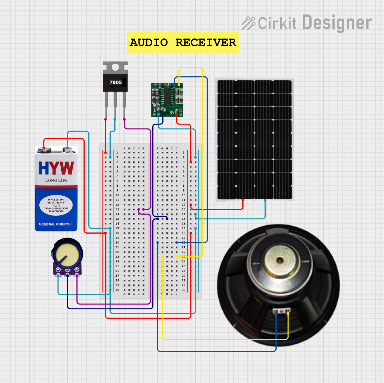
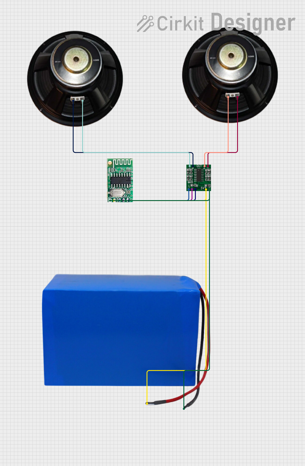
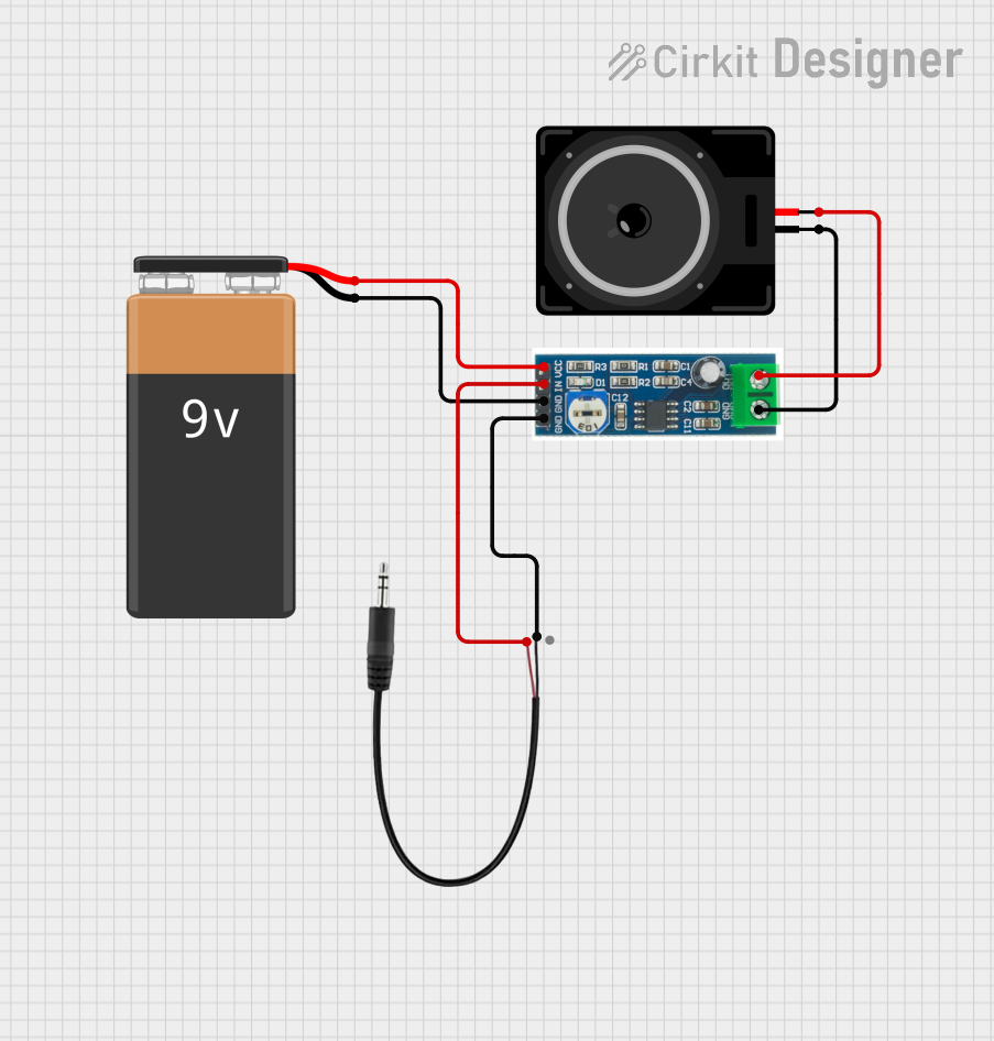
- Audio equipment (e.g., speakers, microphones, and headphones)
- Radio frequency (RF) transmission and reception
- Signal processing in sensors and instrumentation
- Communication systems (e.g., mobile phones, modems)
- Medical devices (e.g., ECG and EEG amplifiers)
Explore Projects Built with Amplifier
Explore Projects Built with Amplifier
Technical Specifications
The technical specifications of an amplifier can vary depending on its type and application. Below are general specifications for a basic operational amplifier (op-amp), which is a common type of amplifier:
General Specifications
- Supply Voltage (Vcc): ±5V to ±15V (typical for op-amps)
- Input Impedance: 1 MΩ or higher
- Output Impedance: Low (typically < 100 Ω)
- Gain (Voltage Amplification): Adjustable, up to 100,000 or more
- Bandwidth: DC to several MHz (depending on the model)
- Slew Rate: 0.5 V/µs to 20 V/µs
- Power Consumption: Varies by model, typically a few milliwatts
Pin Configuration
Below is the pin configuration for a standard 8-pin dual in-line package (DIP) operational amplifier, such as the LM741:
| Pin Number | Pin Name | Description |
|---|---|---|
| 1 | Offset Null | Used for offset voltage adjustment |
| 2 | Inverting Input (-) | Input for the inverting signal |
| 3 | Non-Inverting Input (+) | Input for the non-inverting signal |
| 4 | V- (Negative Supply) | Negative power supply (e.g., -15V) |
| 5 | Offset Null | Used for offset voltage adjustment |
| 6 | Output | Amplified output signal |
| 7 | V+ (Positive Supply) | Positive power supply (e.g., +15V) |
| 8 | Not Connected | No internal connection (varies by model) |
Usage Instructions
How to Use an Amplifier in a Circuit
Power Supply:
- Connect the positive supply voltage (V+) to the appropriate pin (e.g., Pin 7 for LM741).
- Connect the negative supply voltage (V-) to the corresponding pin (e.g., Pin 4 for LM741).
- Ensure the power supply voltage is within the specified range for the amplifier.
Input Signal:
- Connect the input signal to the inverting (-) or non-inverting (+) input, depending on the desired configuration (inverting or non-inverting amplifier).
Feedback Resistor:
- Use a feedback resistor between the output and the inverting input to set the gain of the amplifier. For example:
- Gain = 1 + (Rf / Rin) for a non-inverting amplifier
- Gain = -(Rf / Rin) for an inverting amplifier
- Use a feedback resistor between the output and the inverting input to set the gain of the amplifier. For example:
Output Signal:
- Connect the load (e.g., speaker, sensor, or other circuit) to the output pin.
Bypass Capacitors:
- Place bypass capacitors (e.g., 0.1 µF) near the power supply pins to reduce noise and improve stability.
Important Considerations and Best Practices
- Avoid exceeding the maximum supply voltage to prevent damage to the amplifier.
- Use proper grounding techniques to minimize noise and interference.
- Select appropriate resistor and capacitor values to achieve the desired gain and frequency response.
- For high-frequency applications, consider the amplifier's bandwidth and slew rate.
Example: Connecting an Amplifier to an Arduino UNO
Below is an example of using an LM358 op-amp to amplify an analog signal for an Arduino UNO:
// Example: Amplifying a signal with an LM358 and reading it with Arduino UNO

const int analogPin = A0; // Analog pin to read the amplified signal
int signalValue = 0;      // Variable to store the signal value

void setup() {
  Serial.begin(9600); // Initialize serial communication at 9600 baud
}

void loop() {
  signalValue = analogRead(analogPin); // Read the amplified signal
  Serial.print("Amplified Signal Value: ");
  Serial.println(signalValue); // Print the signal value to the Serial Monitor
  delay(500); // Wait for 500ms before the next reading
}
Note: Ensure the LM358 is properly connected in a non-inverting or inverting configuration, and the output is fed to the Arduino's analog input pin.
Troubleshooting and FAQs
Common Issues and Solutions
No Output Signal:
- Check the power supply connections and ensure the amplifier is powered correctly.
- Verify that the input signal is present and within the amplifier's input range.
- Ensure the feedback resistor is properly connected.
Distorted Output:
- Check if the input signal exceeds the amplifier's input voltage range.
- Verify that the gain is not set too high, which can cause clipping.
- Use bypass capacitors to reduce noise and improve stability.
Excessive Noise:
- Ensure proper grounding and shielding of the circuit.
- Use low-noise resistors and capacitors in the circuit design.
Overheating:
- Verify that the amplifier is not overloaded by the connected load.
- Ensure the power supply voltage is within the specified range.
FAQs
Q: Can I use an amplifier to boost a digital signal?
A: Amplifiers are typically used for analog signals. For digital signals, use a logic level shifter or buffer.
Q: How do I choose the right amplifier for my application?
A: Consider factors such as gain, bandwidth, input/output impedance, power supply requirements, and noise performance.
Q: What is the difference between an inverting and non-inverting amplifier?
A: An inverting amplifier inverts the phase of the input signal, while a non-inverting amplifier maintains the same phase.
Q: Can I use an amplifier with a single power supply?
A: Yes, many amplifiers (e.g., LM358) can operate with a single supply. Ensure the input and output signals are biased appropriately.