
How to Use SWITCH-SPST-2: Examples, Pinouts, and Specs
 Design with SWITCH-SPST-2 in Cirkit Designer
Introduction
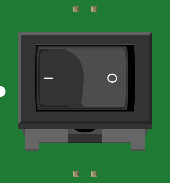
The SWITCH-SPST-2 is a Single Pole Single Throw (SPST) switch designed to control a single circuit. It operates as a simple on/off mechanism, allowing the circuit to be either open (off) or closed (on). This switch is widely used in electronic devices for straightforward on/off control, such as power switches, user input controls, and circuit isolation.
Explore Projects Built with SWITCH-SPST-2
 Open Project in Cirkit Designer
 Open Project in Cirkit Designer
 Open Project in Cirkit Designer
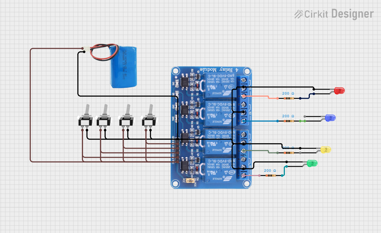 Open Project in Cirkit Designer
Explore Projects Built with SWITCH-SPST-2
Open Project in Cirkit DesignerOpen Project in Cirkit DesignerOpen Project in Cirkit DesignerOpen Project in Cirkit DesignerCommon Applications
- Power control for electronic devices
- User input for simple control panels
- Circuit isolation in testing and debugging
- Light switches and other household applications
Technical Specifications
The SWITCH-SPST-2 is a mechanical switch with the following key specifications:
| Parameter | Value |
|---|---|
| Switch Type | Single Pole Single Throw (SPST) |
| Operating Voltage | 0V to 250V AC/DC |
| Maximum Current | 5A |
| Contact Resistance | ≤ 50 mΩ |
| Insulation Resistance | ≥ 100 MΩ |
| Mechanical Life | 10,000 cycles |
| Mounting Type | Through-hole or panel mount |
| Dimensions | 12mm x 6mm x 6mm |
Pin Configuration and Descriptions
The SWITCH-SPST-2 typically has two terminals (pins) for connection:
| Pin | Description |
|---|---|
| Pin 1 | Input terminal for the circuit |
| Pin 2 | Output terminal for the circuit |
When the switch is in the "on" position, Pin 1 and Pin 2 are electrically connected, allowing current to flow. In the "off" position, the connection is broken, and no current flows.
Usage Instructions
How to Use the SWITCH-SPST-2 in a Circuit
- Identify the Terminals: Locate the two terminals (Pin 1 and Pin 2) on the switch.
- Connect the Circuit:
- Connect Pin 1 to the power source or input signal.
- Connect Pin 2 to the load or output circuit.
- Mount the Switch: Secure the switch to a panel or PCB using the appropriate mounting method.
- Test the Circuit: Toggle the switch to ensure it properly opens and closes the circuit.
Important Considerations
- Voltage and Current Ratings: Ensure the operating voltage and current of your circuit do not exceed the switch's maximum ratings (250V, 5A).
- Debouncing: Mechanical switches may produce noise or "bouncing" when toggled. Use a capacitor or software debouncing techniques if the switch is used for digital input.
- Mounting: Avoid excessive force when mounting the switch to prevent damage to the terminals or housing.
- Safety: When working with high voltages, ensure proper insulation and safety precautions.
Example: Connecting to an Arduino UNO
The SWITCH-SPST-2 can be used as a digital input for an Arduino UNO. Below is an example circuit and code:
Circuit Setup
- Connect one terminal of the switch to a digital input pin on the Arduino (e.g., Pin 2).
- Connect the other terminal of the switch to GND.
- Use a pull-up resistor (10kΩ) between the digital input pin and 5V to ensure a stable HIGH signal when the switch is open.
Arduino Code
// Define the pin connected to the switch
const int switchPin = 2;

// Variable to store the switch state
int switchState = 0;

void setup() {
  // Set the switch pin as input with an internal pull-up resistor
  pinMode(switchPin, INPUT_PULLUP);

  // Initialize serial communication for debugging
  Serial.begin(9600);
}

void loop() {
  // Read the state of the switch
  switchState = digitalRead(switchPin);

  // Print the switch state to the Serial Monitor
  if (switchState == LOW) {
    // Switch is pressed (closed)
    Serial.println("Switch is ON");
  } else {
    // Switch is not pressed (open)
    Serial.println("Switch is OFF");
  }

  // Add a small delay to avoid spamming the Serial Monitor
  delay(200);
}
Troubleshooting and FAQs
Common Issues
Switch Not Working
- Cause: Loose or incorrect wiring.
- Solution: Double-check the connections to ensure the switch terminals are properly connected to the circuit.
Intermittent Operation
- Cause: Contact wear or dirt on the terminals.
- Solution: Clean the switch contacts or replace the switch if worn out.
No Response in Arduino Circuit
- Cause: Missing pull-up resistor or incorrect pin configuration.
- Solution: Ensure a pull-up resistor is used and verify the Arduino pin setup in the code.
Switch Generates Noise in Digital Circuits
- Cause: Mechanical bouncing of the switch.
- Solution: Implement hardware (capacitor) or software debouncing techniques.
FAQs
Q: Can the SWITCH-SPST-2 handle AC and DC currents?
A: Yes, the switch is designed to handle both AC and DC currents, up to a maximum of 250V and 5A.
Q: How do I know if the switch is in the "on" position?
A: When the switch is in the "on" position, the circuit is closed, and current flows between Pin 1 and Pin 2. You can verify this with a multimeter or by observing the circuit's operation.
Q: Can I use the SWITCH-SPST-2 for high-frequency signals?
A: The switch is primarily designed for low-frequency or DC applications. For high-frequency signals, consider using a switch specifically designed for RF or high-speed applications.
Q: What is the lifespan of the SWITCH-SPST-2?
A: The switch has a mechanical life of approximately 10,000 cycles under normal operating conditions.