How to Use esp-pico-kit-v4: Examples, Pinouts, and Specs
Introduction
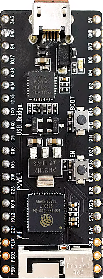
The ESP-PICO-KIT-V4 is a compact development board built around the ESP32-PICO-D4 system-on-chip (SoC). This SoC integrates Wi-Fi and Bluetooth capabilities, making it ideal for IoT (Internet of Things) applications. The board is designed for rapid prototyping and development, offering a small form factor, GPIO pins for interfacing with peripherals, USB connectivity for programming and debugging, and compatibility with a wide range of sensors and modules.
Explore Projects Built with esp-pico-kit-v4


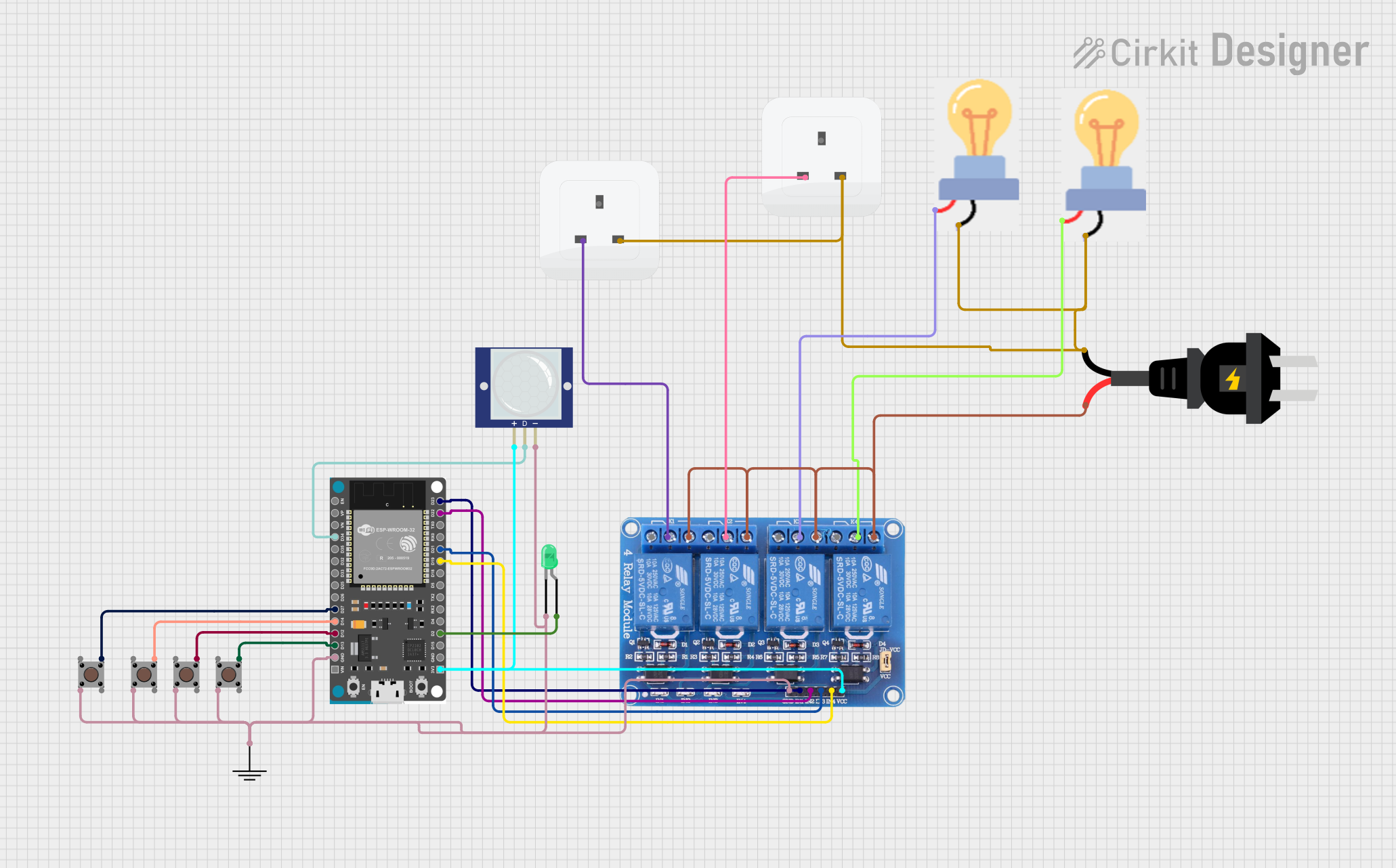
Explore Projects Built with esp-pico-kit-v4
Common Applications and Use Cases
- IoT devices and smart home applications
- Wireless sensor networks
- Wearable electronics
- Industrial automation
- Prototyping Bluetooth and Wi-Fi-enabled devices
Technical Specifications
Key Technical Details
- Microcontroller: ESP32-PICO-D4 (dual-core Xtensa® 32-bit LX6 processor)
- Clock Speed: Up to 240 MHz
- Flash Memory: 4 MB (integrated in the ESP32-PICO-D4)
- RAM: 520 KB SRAM
- Wireless Connectivity:
- Wi-Fi: 802.11 b/g/n
- Bluetooth: v4.2 BR/EDR and BLE
- Operating Voltage: 3.3V
- USB Interface: Micro-USB for programming and power
- GPIO Pins: 20 (multiplexed for various functions)
- Dimensions: 52 mm x 20 mm
Pin Configuration and Descriptions
The ESP-PICO-KIT-V4 exposes 20 GPIO pins, which can be used for digital I/O, analog input, PWM, I2C, SPI, UART, and more. Below is the pinout description:
| Pin | Name | Function |
|---|---|---|
| 1 | GND | Ground |
| 2 | 3V3 | 3.3V power output |
| 3 | EN | Enable pin (active high, used to reset the chip) |
| 4 | IO0 | GPIO0, used for boot mode selection during programming |
| 5 | IO1 (TXD0) | GPIO1, UART0 TX (default serial output) |
| 6 | IO3 (RXD0) | GPIO3, UART0 RX (default serial input) |
| 7 | IO4 | GPIO4, supports PWM, I2C, and other functions |
| 8 | IO5 | GPIO5, supports PWM, SPI, and other functions |
| 9 | IO12 | GPIO12, supports ADC, PWM, and other functions |
| 10 | IO13 | GPIO13, supports ADC, PWM, and other functions |
| 11 | IO14 | GPIO14, supports ADC, PWM, and other functions |
| 12 | IO15 | GPIO15, supports ADC, PWM, and other functions |
| 13 | IO16 | GPIO16, supports ADC, PWM, and other functions |
| 14 | IO17 | GPIO17, supports ADC, PWM, and other functions |
| 15 | IO18 | GPIO18, supports SPI, PWM, and other functions |
| 16 | IO19 | GPIO19, supports SPI, PWM, and other functions |
| 17 | IO21 | GPIO21, supports I2C, PWM, and other functions |
| 18 | IO22 | GPIO22, supports I2C, PWM, and other functions |
| 19 | IO23 | GPIO23, supports SPI, PWM, and other functions |
| 20 | IO25 | GPIO25, supports ADC, PWM, and other functions |
Usage Instructions
How to Use the ESP-PICO-KIT-V4 in a Circuit
Powering the Board:
- Connect the board to your computer or a USB power source using a Micro-USB cable.
- Ensure the power supply provides 5V via USB, which the onboard regulator converts to 3.3V.
Programming the Board:
- Install the Arduino IDE or ESP-IDF for development.
- Add the ESP32 board support package to the Arduino IDE via the Boards Manager.
- Select "ESP32 Dev Module" as the board in the Arduino IDE.
- Connect the board to your computer and select the appropriate COM port.
Connecting Peripherals:
- Use jumper wires to connect sensors, actuators, or other modules to the GPIO pins.
- Refer to the pin configuration table to determine the appropriate pins for your application.
Uploading Code:
- Write your code in the Arduino IDE or ESP-IDF.
- Press the "Upload" button in the IDE to flash the code to the board.
- If the upload fails, hold down the "BOOT" button on the board while uploading.
Example Code for Arduino IDE
The following example demonstrates how to blink an LED connected to GPIO2:
// Define the GPIO pin for the LED
const int ledPin = 2;

void setup() {
  // Set the LED pin as an output
  pinMode(ledPin, OUTPUT);
}

void loop() {
  // Turn the LED on
  digitalWrite(ledPin, HIGH);
  delay(1000); // Wait for 1 second

  // Turn the LED off
  digitalWrite(ledPin, LOW);
  delay(1000); // Wait for 1 second
}
Important Considerations and Best Practices
- Voltage Levels: Ensure all connected peripherals operate at 3.3V logic levels to avoid damaging the board.
- Boot Mode: GPIO0 must be pulled low during programming. This is handled automatically when using the onboard USB interface.
- Heat Management: The ESP32-PICO-D4 can get warm during operation. Ensure adequate ventilation if used in an enclosed space.
Troubleshooting and FAQs
Common Issues and Solutions
The board is not detected by the computer:
- Ensure the USB cable is functional and supports data transfer.
- Install the necessary USB-to-serial drivers (e.g., CP210x or CH340).
Code upload fails:
- Check that the correct COM port is selected in the IDE.
- Hold down the "BOOT" button while uploading the code.
Wi-Fi or Bluetooth is not working:
- Verify that the correct SSID and password are used in your code for Wi-Fi.
- Ensure no other devices are interfering with the Bluetooth connection.
The board overheats:
- Reduce the clock speed in your code if possible.
- Avoid running high-power tasks continuously without breaks.
FAQs
Q: Can I power the board using an external 3.3V source?
A: Yes, you can power the board via the 3V3 pin, but ensure the voltage is stable and does not exceed 3.3V.
Q: How do I reset the board?
A: Press the "EN" button on the board to reset it.
Q: Can I use the ESP-PICO-KIT-V4 with MicroPython?
A: Yes, the board supports MicroPython. You can flash the MicroPython firmware using tools like esptool.py.
Q: What is the maximum current output of the GPIO pins?
A: Each GPIO pin can source or sink up to 12 mA. Avoid exceeding this limit to prevent damage.