How to Use RCD Type B for EV: Examples, Pinouts, and Specs
Introduction
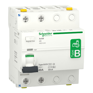
A Residual Current Device (RCD) Type B is a safety-critical component designed to protect electric vehicle (EV) charging installations from earth faults and residual currents. Unlike standard RCDs, Type B devices are capable of detecting both alternating current (AC) and direct current (DC) leakage, making them essential for modern EV charging systems. They ensure compliance with electrical safety standards and provide robust protection against electrical hazards.
Explore Projects Built with RCD Type B for EV


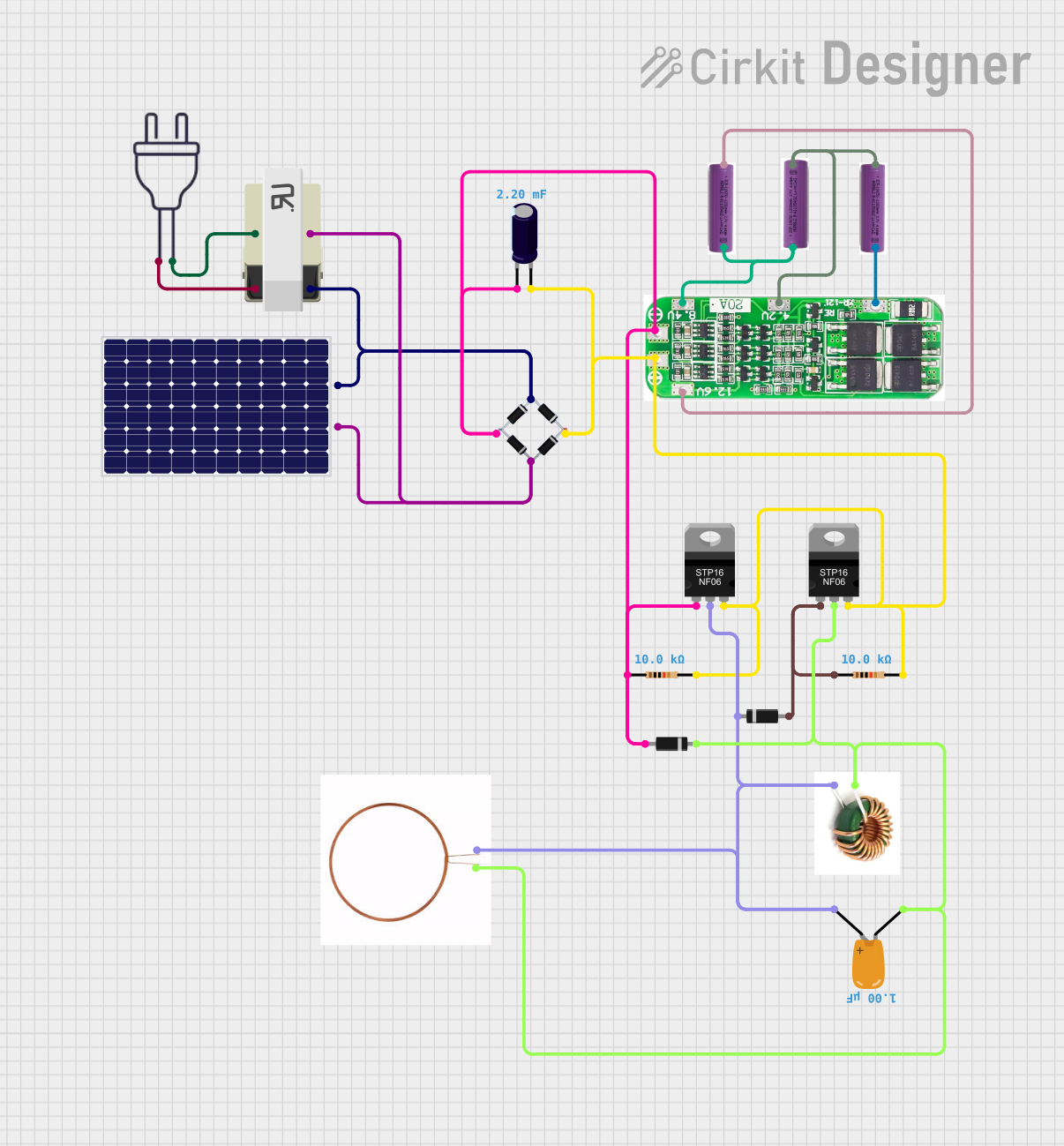
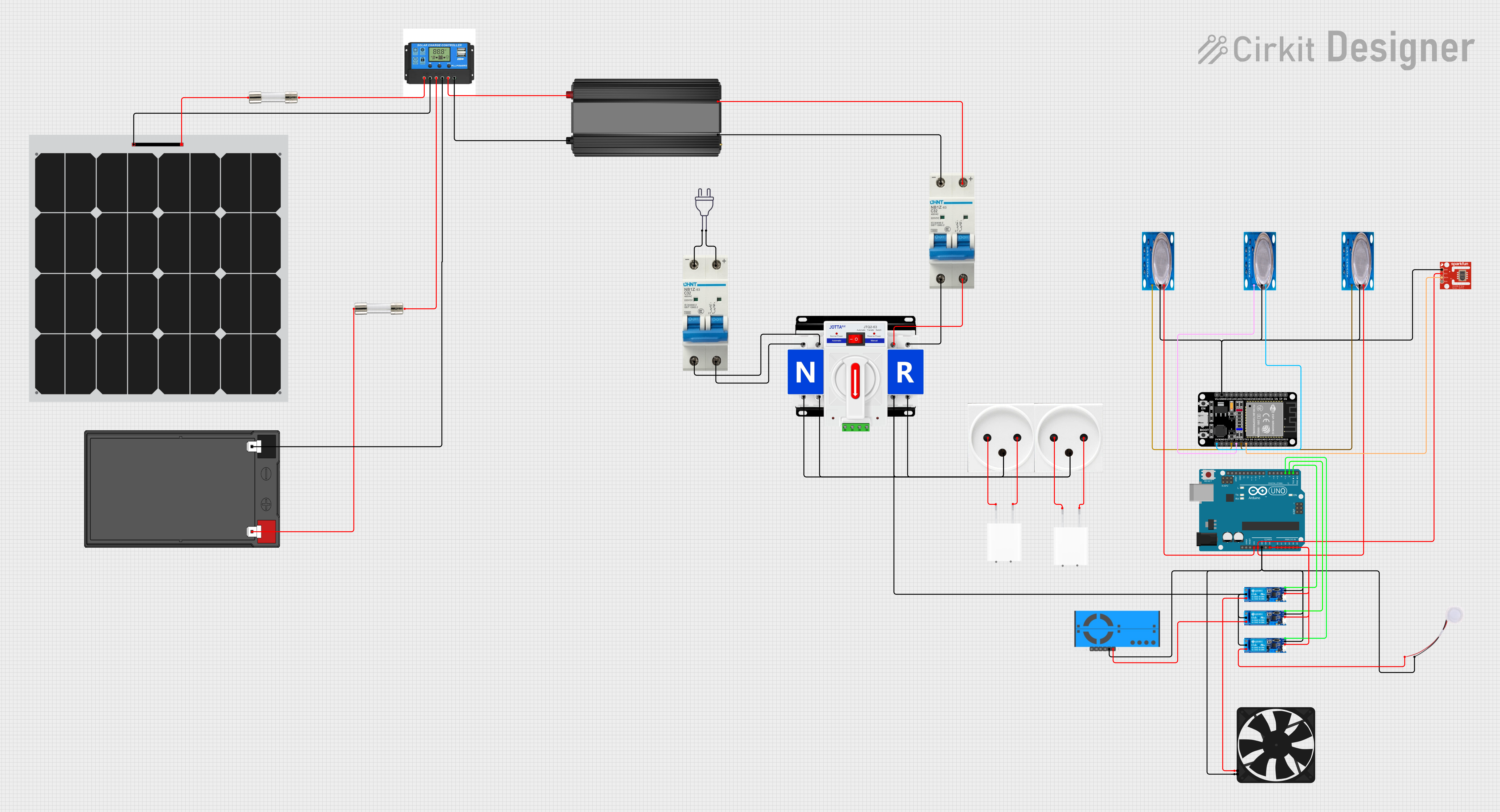
Explore Projects Built with RCD Type B for EV
Common Applications and Use Cases
- EV charging stations (residential, commercial, and public installations)
- Protection of three-phase and single-phase charging systems
- Industrial applications requiring DC fault detection
- Renewable energy systems, such as solar inverters, where DC leakage may occur
Technical Specifications
Key Technical Details
| Parameter | Value/Description |
|---|---|
| Rated Voltage | 230V AC (single-phase) / 400V AC (three-phase) |
| Rated Current | 16A, 32A, or 63A (varies by model) |
| Residual Current Sensitivity | 30mA (AC), 6mA (DC) |
| Frequency Range | 50Hz/60Hz |
| Operating Temperature Range | -25°C to +40°C |
| Compliance Standards | IEC 61008-1, IEC 62423 |
| Mounting Type | DIN rail |
| Dimensions | Typically 4-6 modules wide (varies by model) |
Pin Configuration and Descriptions
| Pin/Terminal Label | Description |
|---|---|
| L (Line) | Connects to the live input from the power supply |
| N (Neutral) | Connects to the neutral input from the power supply |
| Load L | Connects to the live output to the load (e.g., EV charger) |
| Load N | Connects to the neutral output to the load |
| Test Button | Used to manually test the functionality of the RCD |
Usage Instructions
How to Use the Component in a Circuit
Wiring the RCD Type B:
- Connect the live (L) and neutral (N) input terminals to the power supply.
- Connect the load terminals (Load L and Load N) to the EV charger or other load.
- Ensure proper grounding of the system for optimal safety.
Testing the RCD:
- Use the built-in test button to verify the functionality of the RCD. Pressing the button should trip the device, disconnecting the load. Reset the RCD after testing.
Installation Guidelines:
- Mount the RCD on a DIN rail in the distribution board.
- Ensure the device is rated for the current and voltage of your EV charging system.
- Follow local electrical codes and standards during installation.
Important Considerations and Best Practices
- Always use an RCD Type B for EV charging installations to detect both AC and DC leakage currents.
- Regularly test the RCD using the test button to ensure it is functioning correctly.
- Avoid overloading the RCD by ensuring the connected load does not exceed its rated current.
- Use appropriate cable sizes and ensure secure connections to prevent overheating or loose contacts.
- If integrating with an Arduino-based EV charger monitoring system, ensure the RCD is installed upstream to provide fault protection.
Example Arduino Code for Monitoring RCD Status
If you are using an Arduino to monitor the status of the RCD (e.g., detecting if it trips), you can use a digital input pin to read the state of the RCD's auxiliary contact (if available).
// Define the pin connected to the RCD auxiliary contact
const int rcdStatusPin = 2; // Digital pin 2

void setup() {
  pinMode(rcdStatusPin, INPUT_PULLUP); // Configure pin as input with pull-up resistor
  Serial.begin(9600); // Initialize serial communication
}

void loop() {
  int rcdStatus = digitalRead(rcdStatusPin); // Read the RCD status pin

  if (rcdStatus == HIGH) {
    // RCD is in normal operation (not tripped)
    Serial.println("RCD Status: Normal");
  } else {
    // RCD has tripped
    Serial.println("RCD Status: Tripped");
  }

  delay(1000); // Wait for 1 second before checking again
}
Note: The auxiliary contact is an optional feature on some RCDs. Check your RCD model for compatibility.
Troubleshooting and FAQs
Common Issues and Solutions
| Issue | Possible Cause | Solution |
|---|---|---|
| RCD trips frequently | Faulty wiring or load with leakage current | Inspect wiring and connected devices |
| RCD does not trip during testing | Faulty RCD or incorrect installation | Replace the RCD or verify connections |
| RCD trips even with no load | Ground fault or insulation failure | Check for ground faults or damaged cables |
| Test button does not work | Internal fault in the RCD | Replace the RCD |
FAQs
Why is a Type B RCD required for EV charging?
Type B RCDs can detect both AC and DC leakage currents, which are common in EV chargers due to their power electronics. This ensures comprehensive protection.Can I use a Type A or Type AC RCD instead?
No, Type A and Type AC RCDs cannot detect DC leakage currents, making them unsuitable for EV charging installations.How often should I test the RCD?
It is recommended to test the RCD monthly using the test button to ensure it is functioning correctly.What happens if the RCD trips?
If the RCD trips, it disconnects the load to prevent electrical hazards. Investigate the cause of the trip before resetting the device.
By following this documentation, you can ensure the safe and effective use of an RCD Type B in your EV charging installation.