How to Use Dino: Examples, Pinouts, and Specs
Introduction
Dino is a fictional character often used in educational electronics kits to represent a simple circuit or a playful mascot for learning about basic electronic components and circuits. Dino is designed to make learning electronics fun and engaging, especially for beginners and young learners. It typically incorporates basic electronic components such as LEDs, resistors, and switches, allowing users to explore fundamental circuit concepts.
Explore Projects Built with Dino

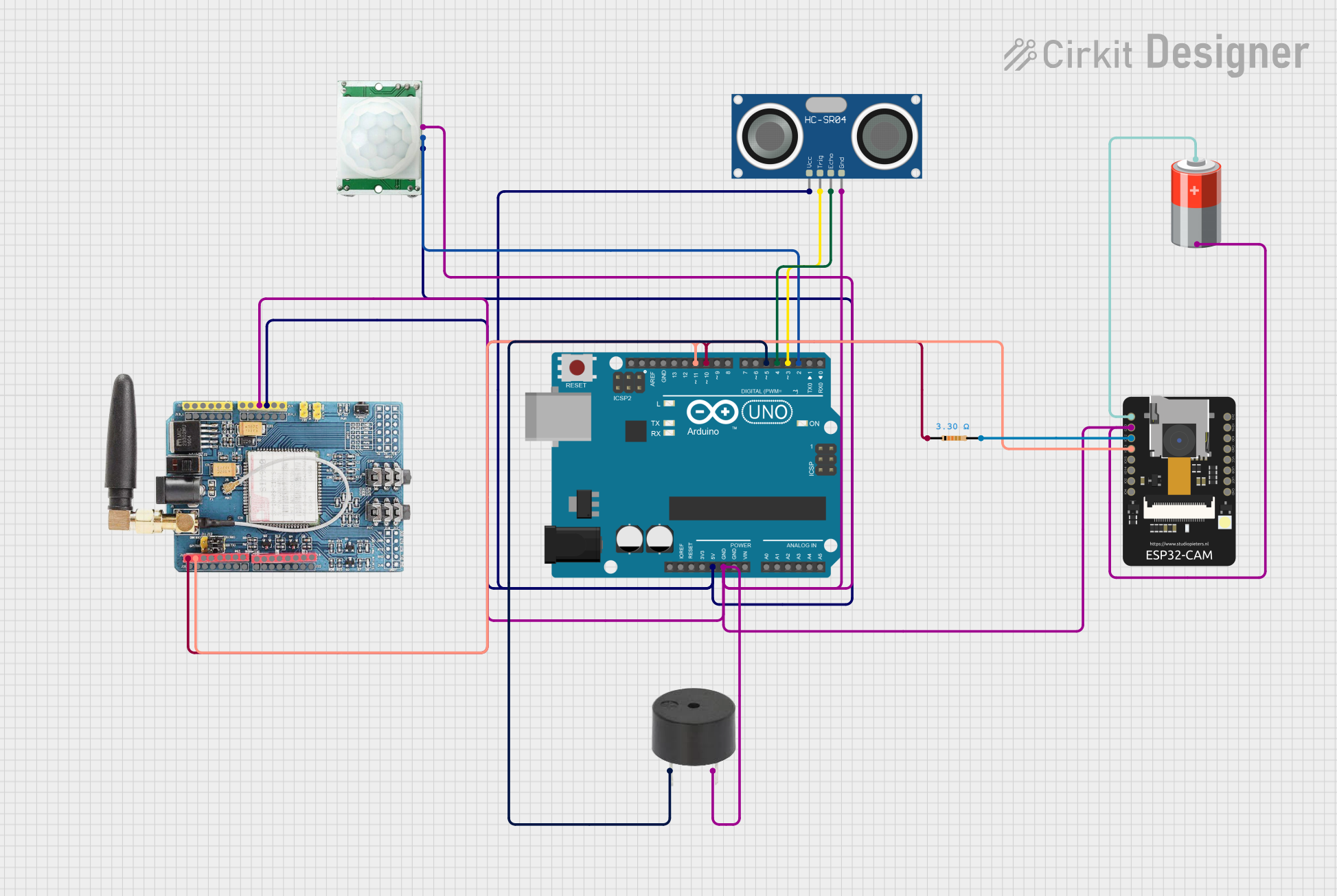
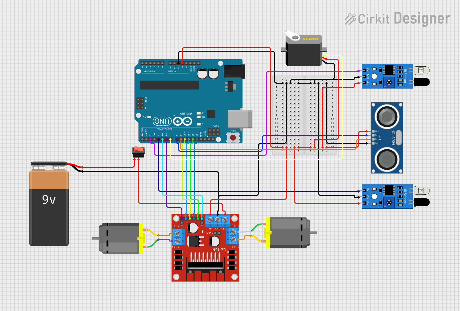
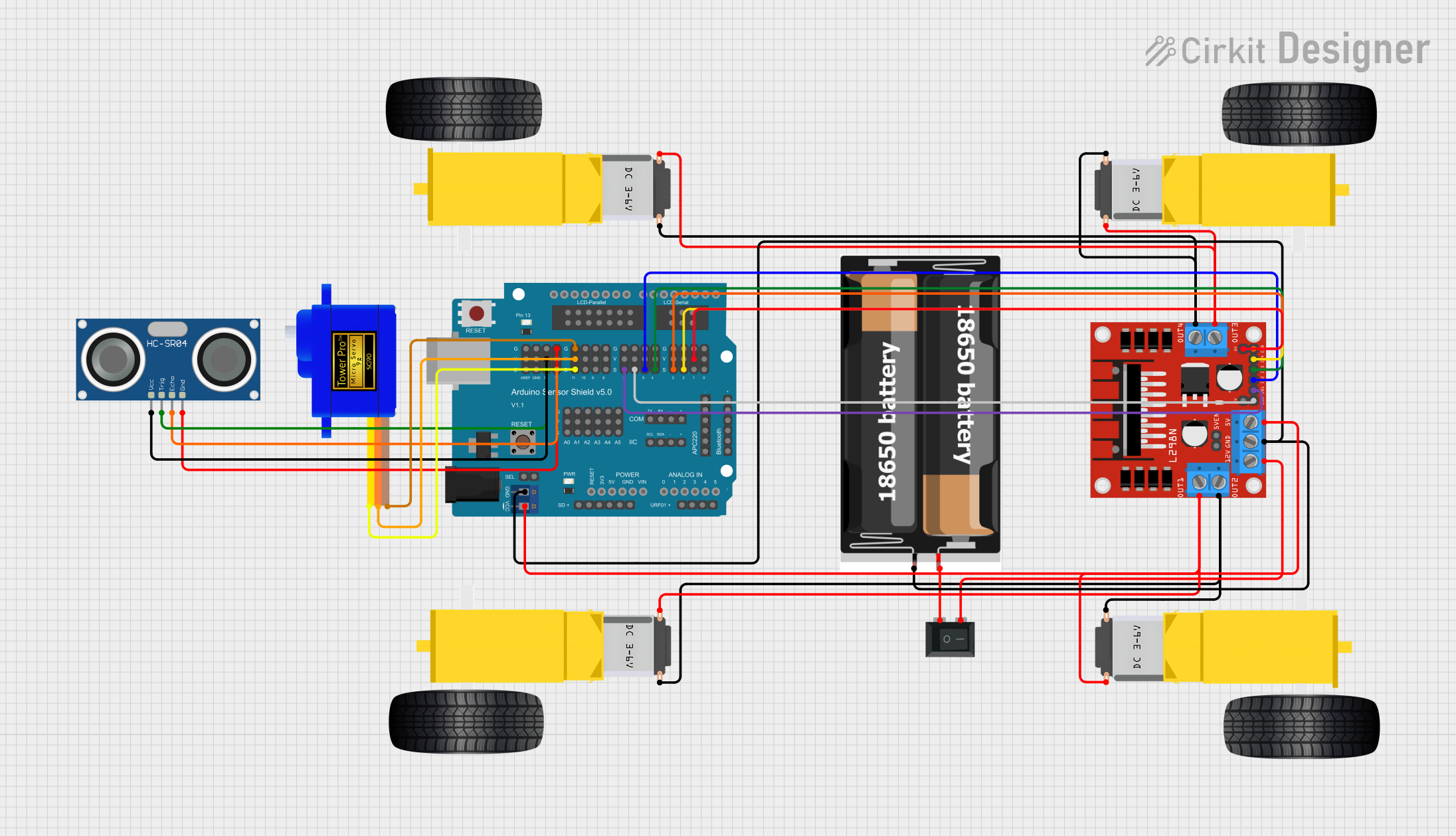
Explore Projects Built with Dino
Common Applications and Use Cases
- Educational tools for teaching basic electronics
- Hands-on learning in STEM workshops and classrooms
- Demonstrating simple circuit principles like current flow and resistance
- Interactive projects for beginners to build confidence in electronics
Technical Specifications
Dino is not a single electronic component but rather a representation of a simple circuit. Below are the typical specifications for a Dino-based educational circuit:
General Specifications
- Operating Voltage: 3V to 5V (commonly powered by batteries or USB)
- Current Consumption: Depends on the components used (e.g., LEDs, resistors)
- Components Included: LEDs, resistors, push-button switches, and a power source
- Circuit Type: Basic series or parallel circuit
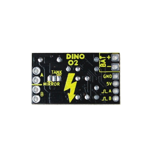
Pin Configuration and Descriptions
If Dino is represented as a PCB or breadboard layout, the following table describes the typical pin connections:
| Pin Name | Description |
|---|---|
| VCC | Positive voltage input (3V to 5V) |
| GND | Ground connection |
| LED+ | Positive terminal of the LED |
| LED- | Negative terminal of the LED |
| SW1 | Push-button switch input |
| R1 | Resistor connected in series with the LED |
Usage Instructions
How to Use Dino in a Circuit
Assemble the Circuit:
- Connect the VCC pin to a 3V or 5V power source.
- Connect the GND pin to the ground of the power source.
- Place the LED in the circuit, ensuring the positive terminal (anode) is connected to the VCC through a resistor (R1) and the negative terminal (cathode) is connected to GND.
- Add a push-button switch (SW1) in series with the LED to control its operation.
Power the Circuit:
- Use a battery pack or USB power supply to provide the required voltage.
Test the Circuit:
- Press the push-button switch to complete the circuit and observe the LED lighting up.
Important Considerations and Best Practices
- Resistor Selection: Use an appropriate resistor value (e.g., 220Ω or 330Ω) to limit the current through the LED and prevent damage.
- Polarity: Ensure correct polarity for the LED and power connections.
- Safety: Avoid short circuits and ensure the power source does not exceed the recommended voltage.
Example Code for Arduino UNO
If Dino is connected to an Arduino UNO, the following code can be used to control the LED:
// Define the pin connected to the LED
const int ledPin = 13; // Pin 13 is commonly used for onboard LEDs

// Define the pin connected to the push-button switch
const int buttonPin = 7;

// Variable to store the button state
int buttonState = 0;

void setup() {
  // Set the LED pin as an output
  pinMode(ledPin, OUTPUT);

  // Set the button pin as an input
  pinMode(buttonPin, INPUT);
}

void loop() {
  // Read the state of the button
  buttonState = digitalRead(buttonPin);

  // If the button is pressed, turn on the LED
  if (buttonState == HIGH) {
    digitalWrite(ledPin, HIGH); // Turn on the LED
  } else {
    digitalWrite(ledPin, LOW);  // Turn off the LED
  }
}
Troubleshooting and FAQs
Common Issues Users Might Face
LED Does Not Light Up:
- Cause: Incorrect polarity or loose connections.
- Solution: Check the LED's anode and cathode connections. Ensure all wires are securely connected.
LED Burns Out:
- Cause: No resistor or incorrect resistor value.
- Solution: Use a resistor with an appropriate value (e.g., 220Ω or 330Ω) to limit the current.
Push-Button Switch Does Not Work:
- Cause: Faulty switch or incorrect wiring.
- Solution: Verify the switch connections and test the switch with a multimeter.
Arduino Code Does Not Work:
- Cause: Incorrect pin assignments or syntax errors.
- Solution: Double-check the pin numbers in the code and ensure the Arduino is properly connected to the circuit.
Solutions and Tips for Troubleshooting
- Use a multimeter to check for continuity and voltage levels in the circuit.
- Verify that the power source is functioning and providing the correct voltage.
- Test individual components (e.g., LED, resistor, switch) before assembling the full circuit.
- If using an Arduino, ensure the board is properly powered and the code is uploaded without errors.
By following this documentation, users can successfully assemble and troubleshoot a Dino-based educational circuit, making learning electronics an enjoyable experience!