How to Use RJ45 Ethernet: Examples, Pinouts, and Specs
Introduction
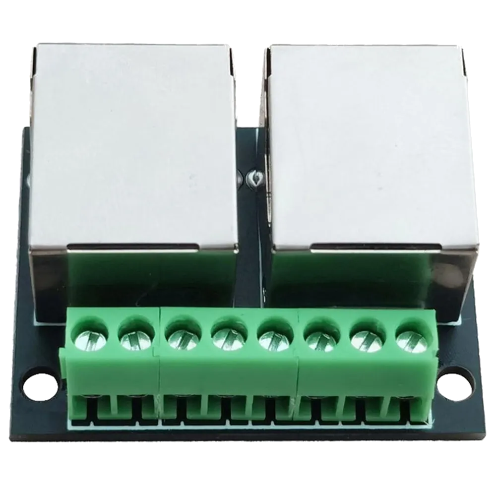
The RJ45 Ethernet connector is a standardized interface widely used for Ethernet networking. It features an 8-pin modular design and is commonly employed to connect computers, routers, switches, and other devices to local area networks (LANs). Its robust design and reliable performance make it a staple in both residential and commercial networking applications.
Explore Projects Built with RJ45 Ethernet
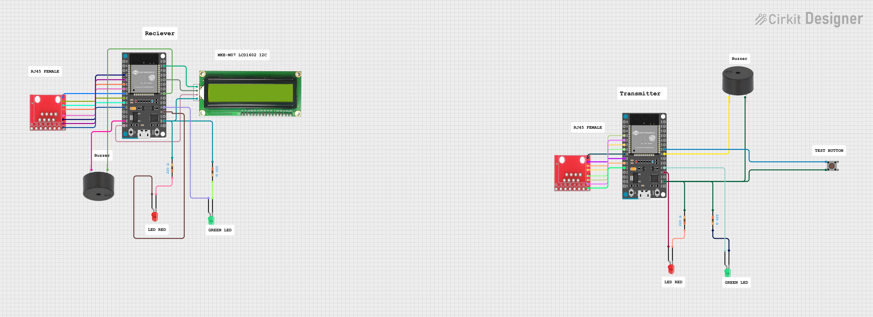
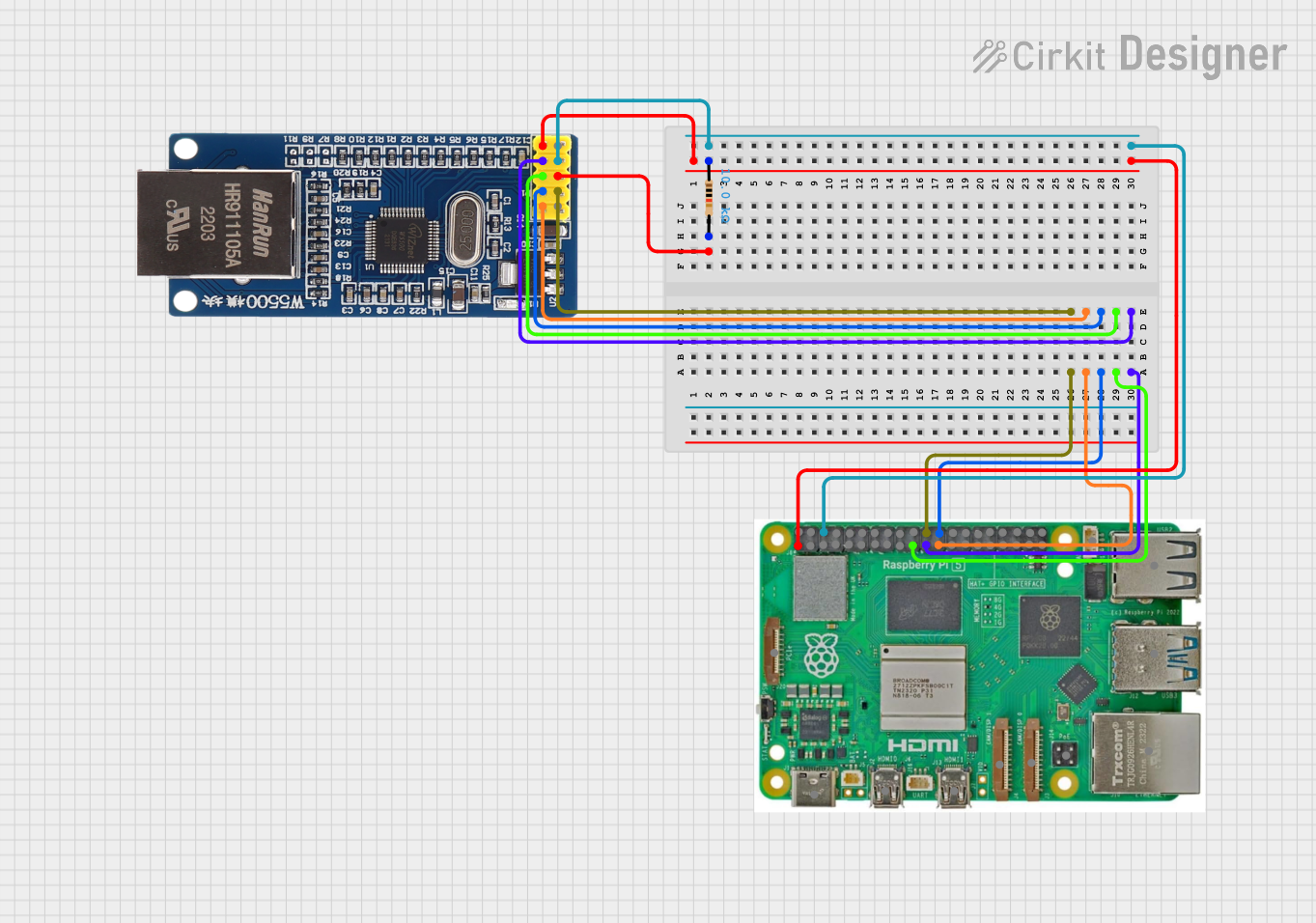


Explore Projects Built with RJ45 Ethernet
Common Applications and Use Cases
- Connecting computers, routers, and switches in LANs
- Establishing wired internet connections
- Industrial and commercial networking setups
- Power over Ethernet (PoE) applications
- Data transfer in high-speed networks
Technical Specifications
The RJ45 Ethernet connector is designed to meet the requirements of Ethernet standards, including 10BASE-T, 100BASE-TX, and 1000BASE-T (Gigabit Ethernet). Below are its key technical details:
Key Technical Details
| Parameter | Specification |
|---|---|
| Connector Type | RJ45 (8P8C - 8 Positions, 8 Contacts) |
| Supported Standards | 10BASE-T, 100BASE-TX, 1000BASE-T |
| Number of Pins | 8 |
| Voltage Rating | 150V (typical) |
| Current Rating | 1.5A (maximum per pin) |
| Operating Temperature | -40°C to +85°C |
| Contact Resistance | ≤ 20 mΩ |
| Insulation Resistance | ≥ 500 MΩ |
| Durability | 750+ mating cycles |
Pin Configuration and Descriptions
The RJ45 connector uses an 8-pin configuration. The pinout follows the T568A or T568B wiring standards, which are commonly used in Ethernet cables.
T568B Wiring Standard (Most Common)
| Pin Number | Wire Color | Signal Description |
|---|---|---|
| 1 | White/Orange | Transmit Data + (TX+) |
| 2 | Orange | Transmit Data - (TX-) |
| 3 | White/Green | Receive Data + (RX+) |
| 4 | Blue | Unused (or PoE Power +) |
| 5 | White/Blue | Unused (or PoE Power +) |
| 6 | Green | Receive Data - (RX-) |
| 7 | White/Brown | Unused (or PoE Power -) |
| 8 | Brown | Unused (or PoE Power -) |
T568A Wiring Standard
| Pin Number | Wire Color | Signal Description |
|---|---|---|
| 1 | White/Green | Transmit Data + (TX+) |
| 2 | Green | Transmit Data - (TX-) |
| 3 | White/Orange | Receive Data + (RX+) |
| 4 | Blue | Unused (or PoE Power +) |
| 5 | White/Blue | Unused (or PoE Power +) |
| 6 | Orange | Receive Data - (RX-) |
| 7 | White/Brown | Unused (or PoE Power -) |
| 8 | Brown | Unused (or PoE Power -) |
Usage Instructions
How to Use the RJ45 Ethernet Connector in a Circuit
- Cable Preparation: Use a Cat5e, Cat6, or higher Ethernet cable for optimal performance. Strip the cable jacket to expose the twisted pairs.
- Wire Arrangement: Arrange the wires according to the T568A or T568B wiring standard. Ensure the wires are untwisted and straightened for proper insertion.
- Connector Crimping: Insert the wires into the RJ45 connector, ensuring each wire aligns with the correct pin. Use an RJ45 crimping tool to secure the connector.
- Testing: Use a cable tester to verify the continuity and correct wiring of the cable.
- Connection: Plug the RJ45 connector into the Ethernet port of the device.
Important Considerations and Best Practices
- Always use high-quality Ethernet cables to ensure reliable data transmission.
- Avoid excessive bending or twisting of the cable to prevent signal degradation.
- For Power over Ethernet (PoE) applications, ensure the connector and cable meet the required power specifications.
- Use a proper crimping tool to avoid damaging the connector or wires.
Example: Connecting an RJ45 Ethernet Module to an Arduino UNO
The RJ45 Ethernet connector is often used with Ethernet modules like the ENC28J60 or W5100 to enable Arduino-based projects to connect to a network. Below is an example of Arduino code for using an Ethernet shield with an RJ45 connector.
#include <SPI.h>
#include <Ethernet.h>

// MAC address and IP address for the Ethernet shield
byte mac[] = { 0xDE, 0xAD, 0xBE, 0xEF, 0xFE, 0xED };
IPAddress ip(192, 168, 1, 177);

// Initialize the Ethernet server on port 80
EthernetServer server(80);

void setup() {
  // Start the Ethernet connection
  Ethernet.begin(mac, ip);

  // Start the server
  server.begin();
  Serial.begin(9600);
  Serial.println("Server is ready at IP: ");
  Serial.println(Ethernet.localIP());
}

void loop() {
  // Listen for incoming clients
  EthernetClient client = server.available();
  if (client) {
    Serial.println("New client connected");
    while (client.connected()) {
      if (client.available()) {
        char c = client.read();
        Serial.write(c); // Echo the received data to the Serial Monitor
      }
    }
    client.stop();
    Serial.println("Client disconnected");
  }
}
Troubleshooting and FAQs
Common Issues and Solutions
Issue: No network connection or intermittent connectivity.
- Solution: Check the wiring and ensure the correct T568A or T568B standard is followed. Verify the cable with a tester.
Issue: Ethernet module not detected by the Arduino.
- Solution: Ensure the RJ45 connector is properly crimped and securely connected. Verify the Ethernet shield is powered and the SPI pins are correctly connected.
Issue: Slow network speeds.
- Solution: Use a higher category cable (e.g., Cat6) and ensure the network hardware supports the desired speed.
Issue: PoE device not powering up.
- Solution: Confirm that the RJ45 connector and cable are rated for PoE. Check the power supply and ensure the correct pins are used for power delivery.
FAQs
Q1: Can I use the RJ45 connector for non-Ethernet applications?
A1: Yes, the RJ45 connector can be used for other applications, such as serial communication or custom wiring, but it is primarily designed for Ethernet networking.
Q2: What is the difference between T568A and T568B wiring standards?
A2: The difference lies in the arrangement of the wire pairs. Both standards are functionally identical for Ethernet, but T568B is more commonly used in the United States.
Q3: How many times can I plug and unplug an RJ45 connector?
A3: The typical durability of an RJ45 connector is rated for 750+ mating cycles.