How to Use Rpi Pico Zero: Examples, Pinouts, and Specs
Introduction
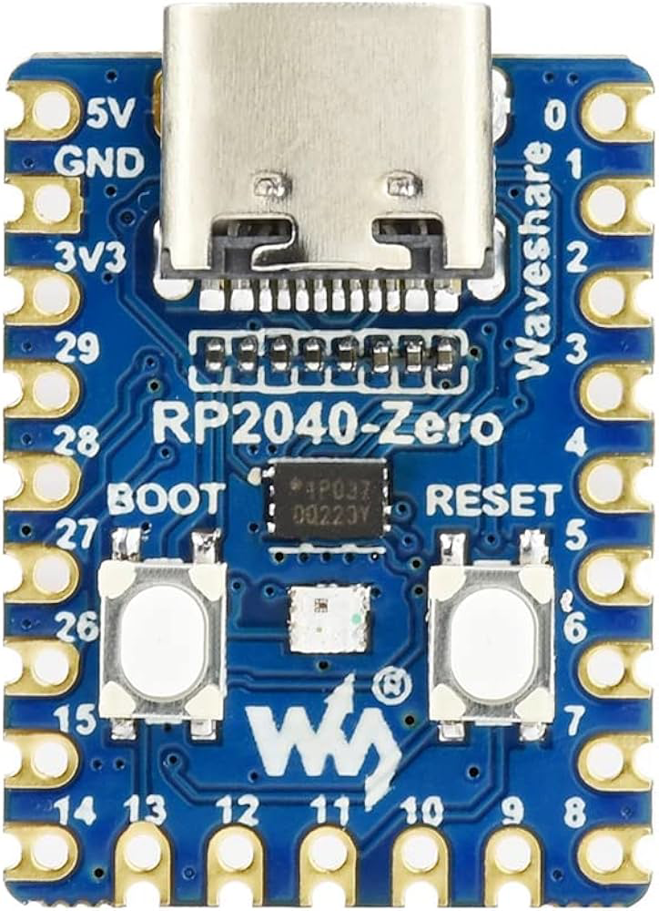
The Raspberry Pi Pico Zero, manufactured by Waveshare (Part ID: 20187), is a compact and versatile microcontroller board based on the RP2040 chip. Designed for low-power applications and embedded systems, it offers a cost-effective solution for hobbyists, students, and professionals alike. The Pico Zero is equipped with GPIO pins for interfacing with a wide range of sensors, actuators, and other peripherals. It supports programming in MicroPython and C/C++, making it accessible to both beginners and experienced developers.
Explore Projects Built with Rpi Pico Zero
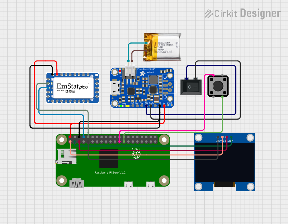

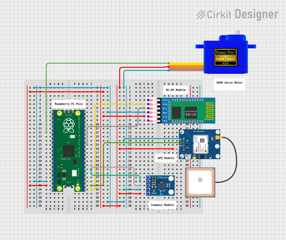
Explore Projects Built with Rpi Pico Zero
Common Applications and Use Cases
- IoT (Internet of Things) devices
- Home automation systems
- Robotics and motor control
- Data logging and environmental monitoring
- Prototyping and educational projects
Technical Specifications
The Rpi Pico Zero is built around the RP2040 microcontroller, which features dual ARM Cortex-M0+ cores and a flexible I/O system. Below are the key technical details:
Key Specifications
| Parameter | Value |
|---|---|
| Microcontroller | RP2040 (Dual ARM Cortex-M0+ cores) |
| Clock Speed | 133 MHz |
| Flash Memory | 2 MB (onboard QSPI flash) |
| SRAM | 264 KB |
| GPIO Pins | 20 |
| Communication Interfaces | I2C, SPI, UART, PWM |
| Operating Voltage | 3.3V |
| Input Voltage Range | 1.8V to 5.5V |
| USB Interface | Micro-USB (for power and data) |
| Programming Languages | MicroPython, C/C++ |
| Dimensions | 51mm x 21mm |
Pin Configuration and Descriptions
The Rpi Pico Zero features a 20-pin GPIO header. Below is the pinout and description:
| Pin Number | Pin Name | Function |
|---|---|---|
| 1 | 3V3 | 3.3V Power Output |
| 2 | GND | Ground |
| 3 | GP0 | GPIO Pin 0 / UART0 TX |
| 4 | GP1 | GPIO Pin 1 / UART0 RX |
| 5 | GP2 | GPIO Pin 2 / I2C1 SDA |
| 6 | GP3 | GPIO Pin 3 / I2C1 SCL |
| 7 | GP4 | GPIO Pin 4 / PWM Output |
| 8 | GP5 | GPIO Pin 5 / PWM Output |
| 9 | GP6 | GPIO Pin 6 / SPI0 SCK |
| 10 | GP7 | GPIO Pin 7 / SPI0 TX |
| 11 | GP8 | GPIO Pin 8 / SPI0 RX |
| 12 | GP9 | GPIO Pin 9 / SPI0 CSn |
| 13 | GP10 | GPIO Pin 10 / UART1 TX |
| 14 | GP11 | GPIO Pin 11 / UART1 RX |
| 15 | GP12 | GPIO Pin 12 / PWM Output |
| 16 | GP13 | GPIO Pin 13 / PWM Output |
| 17 | GP14 | GPIO Pin 14 / I2C0 SDA |
| 18 | GP15 | GPIO Pin 15 / I2C0 SCL |
| 19 | RUN | Reset Pin |
| 20 | VSYS | Input Voltage (1.8V to 5.5V) |
Usage Instructions
How to Use the Rpi Pico Zero in a Circuit
Powering the Board:
- Connect the board to a power source via the Micro-USB port or the VSYS pin. Ensure the input voltage is within the range of 1.8V to 5.5V.
- The onboard 3.3V regulator provides power to the RP2040 and peripherals.
Programming the Board:
- Install the MicroPython firmware or C/C++ SDK on your computer.
- Connect the Pico Zero to your computer via the Micro-USB cable.
- Use an IDE like Thonny (for MicroPython) or Visual Studio Code (for C/C++) to write and upload code.
Connecting Peripherals:
- Use the GPIO pins to interface with sensors, actuators, and other devices.
- Ensure that all connected peripherals operate at 3.3V logic levels to avoid damaging the board.
Important Considerations and Best Practices
- Voltage Levels: The GPIO pins operate at 3.3V. Avoid applying higher voltages to prevent damage.
- Pin Multiplexing: Some pins have multiple functions (e.g., UART, I2C, SPI). Configure the pins appropriately in your code.
- Power Supply: If using the VSYS pin for power, ensure the input voltage is stable and within the specified range.
- Static Protection: Handle the board with care to avoid static discharge, which can damage the microcontroller.
Example Code for Arduino UNO Integration
The Rpi Pico Zero can communicate with an Arduino UNO via I2C. Below is an example of how to set up the Pico Zero as an I2C slave:
Pico Zero (MicroPython) Code:
from machine import I2C, Pin
import utime
Initialize I2C on GPIO pins 4 (SDA) and 5 (SCL)
i2c = I2C(0, scl=Pin(5), sda=Pin(4), freq=100000)
Data to send to the Arduino
data = b"Hello Arduino!"
while True: i2c.writeto(0x08, data) # Send data to I2C address 0x08 utime.sleep(1) # Wait 1 second before sending again
Arduino UNO Code:
#include <Wire.h>

void setup() {
  Wire.begin(0x08); // Initialize as I2C slave with address 0x08
  Wire.onReceive(receiveEvent); // Register receive event handler
  Serial.begin(9600); // Start serial communication for debugging
}

void loop() {
  // Main loop does nothing; data is handled in receiveEvent
}

void receiveEvent(int bytes) {
  while (Wire.available()) {
    char c = Wire.read(); // Read each byte sent by the Pico Zero
    Serial.print(c);      // Print received data to the Serial Monitor
  }
  Serial.println(); // Add a newline after the received message
}
Troubleshooting and FAQs
Common Issues and Solutions
Board Not Detected by Computer:
- Ensure the Micro-USB cable is data-capable (not just for charging).
- Check that the board is in bootloader mode by holding the BOOTSEL button while connecting it to the computer.
GPIO Pins Not Responding:
- Verify that the pins are configured correctly in your code.
- Check for loose or incorrect connections in your circuit.
I2C/SPI Communication Fails:
- Ensure the correct pins are used for the communication protocol.
- Verify that the peripheral device is powered and configured with the correct address.
Overheating or Power Issues:
- Check that the input voltage does not exceed 5.5V.
- Avoid drawing excessive current from the GPIO pins.
FAQs
Can I power the Pico Zero with a battery?
Yes, you can use a battery as long as the voltage is within the range of 1.8V to 5.5V. Connect the battery to the VSYS pin.What is the maximum current output of the GPIO pins?
Each GPIO pin can source or sink up to 12mA, with a total maximum current of 50mA for all pins combined.Can I use the Pico Zero with other programming languages?
While MicroPython and C/C++ are the primary options, you can also use CircuitPython or other RP2040-compatible frameworks.