How to Use Joystick Module V2: Examples, Pinouts, and Specs
Introduction
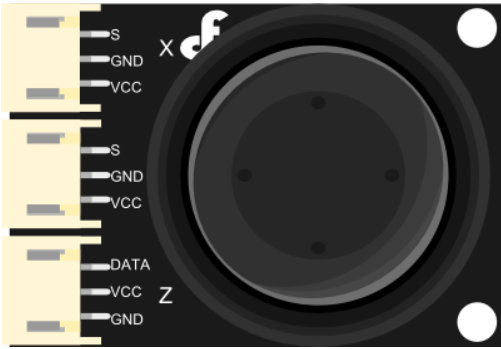
The Joystick Module V2 is an analog input device commonly used in electronic projects for controlling movement in two dimensions. It operates similarly to a game controller joystick, providing X and Y axis movement data. This module is often used in robotics, gaming controls, and as an input device for various DIY projects.
Explore Projects Built with Joystick Module V2


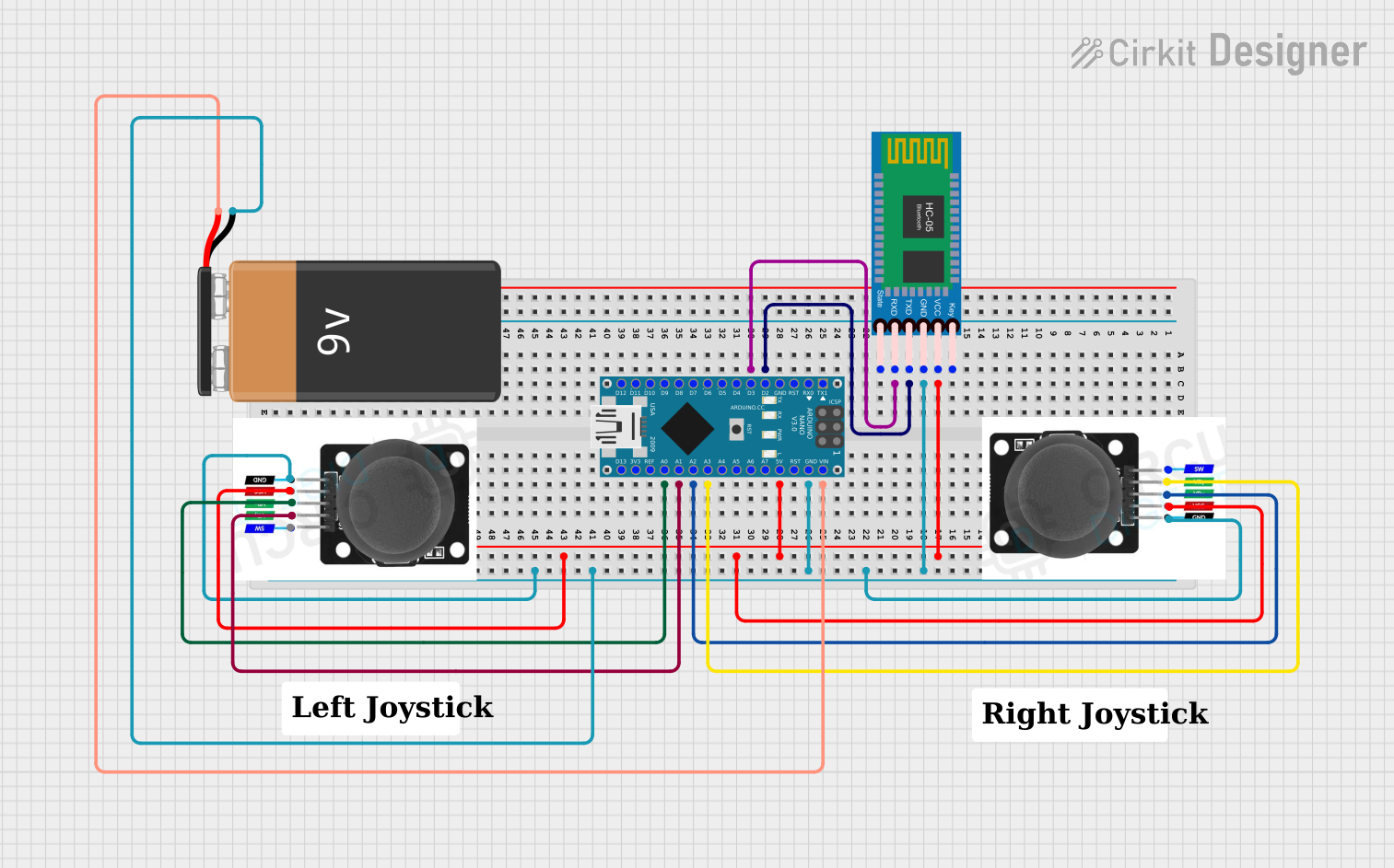
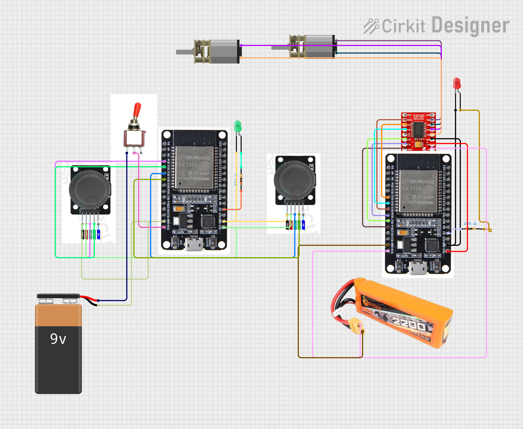
Explore Projects Built with Joystick Module V2
Common Applications and Use Cases
- Robotics control interfaces
- DIY gaming controllers
- Cursor movement on displays
- Educational projects to demonstrate analog input handling
Technical Specifications
Key Technical Details
- Voltage: 3.3V to 5V
- Current: 10mA (typical)
- X and Y Axis Range: 0 to 1023 (analog output)
- Dimensions: Varies by manufacturer, typically around 4cm x 2.5cm x 3.2cm
Pin Configuration and Descriptions
| Pin | Description |
|---|---|
| GND | Ground |
| +5V | Power supply (3.3-5V) |
| VRx | X-axis analog output |
| VRy | Y-axis analog output |
| SW | Pushbutton switch |
Usage Instructions
How to Use the Component in a Circuit
- Connect the
+5Vpin to the 5V output on your microcontroller (e.g., Arduino UNO). - Connect the
GNDpin to a ground pin on your microcontroller. - Connect the
VRxpin to an analog input pin on your microcontroller to read the X-axis. - Connect the
VRypin to another analog input pin to read the Y-axis. - (Optional) Connect the
SWpin to a digital input pin if you wish to use the built-in pushbutton switch.
Important Considerations and Best Practices
- Ensure that the power supply voltage does not exceed the module's voltage rating.
- Use pull-up resistors if necessary for the switch to ensure a stable HIGH signal when not pressed.
- Calibrate the joystick's center position in your code to account for any offset in the resting position.
- Debounce the switch input in software to avoid false triggering from mechanical noise.
Example Code for Arduino UNO
// Define the Arduino analog pins connected to the joystick
const int xAxisPin = A0;
const int yAxisPin = A1;
const int buttonPin = 2; // Digital pin connected to the joystick button

void setup() {
  pinMode(buttonPin, INPUT_PULLUP); // Set the button as an input with internal pull-up
  Serial.begin(9600); // Start serial communication at 9600 baud
}

void loop() {
  // Read the joystick position values
  int xPosition = analogRead(xAxisPin);
  int yPosition = analogRead(yAxisPin);
  // Read the button state (LOW when pressed due to pull-up resistor)
  bool buttonState = !digitalRead(buttonPin);

  // Print the X and Y positions and button state to the serial monitor
  Serial.print("X: ");
  Serial.print(xPosition);
  Serial.print(" Y: ");
  Serial.print(yPosition);
  Serial.print(" Button: ");
  Serial.println(buttonState ? "Pressed" : "Released");

  delay(100); // Add a small delay to make the output readable
}
Troubleshooting and FAQs
Common Issues Users Might Face
- Inaccurate Readings: If the joystick is giving inaccurate readings, check for proper power supply and wiring. Also, ensure that the analog pins are correctly declared in your code.
- Button Not Responding: If the button is not responding, ensure that it is wired correctly with a pull-up resistor, and the digital pin is set up properly in the code.
- Drifting Values: If the joystick values drift, it may need recalibration in the software or there might be an issue with the module itself.
Solutions and Tips for Troubleshooting
- Double-check all connections and ensure they are secure.
- Use the
analogReference()function in Arduino if you need to adjust the reference voltage for the analog inputs. - Implement software debouncing for the button to prevent false triggers.
- Replace the joystick module if it appears to be faulty or damaged.
FAQs
Q: Can I use this joystick with a 3.3V system? A: Yes, the joystick can typically operate at 3.3V, but the analog range will be reduced.
Q: How can I increase the precision of the joystick readings? A: You can increase the precision by using the full range of the analog input and implementing software filtering or averaging.
Q: Is it possible to use the joystick without the button? A: Yes, the button is optional and does not need to be connected for the joystick to function.