How to Use FAN: Examples, Pinouts, and Specs
Introduction
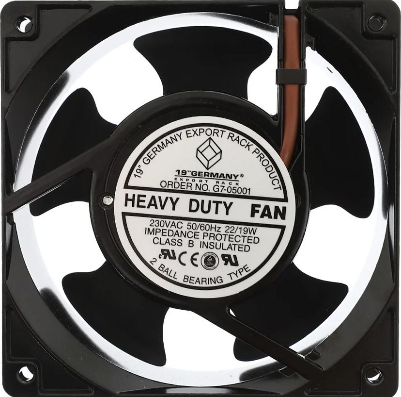
The GERMANY G7-05001 Fan is an electromechanical device designed to create airflow for cooling or ventilation purposes. It is commonly used in electronic devices to dissipate heat generated by components such as processors, power supplies, and other heat-sensitive parts. By maintaining optimal operating temperatures, the fan ensures the longevity and reliability of electronic systems.
Explore Projects Built with FAN


Explore Projects Built with FAN
Common Applications and Use Cases
- Cooling computer processors, GPUs, and power supplies
- Ventilation in enclosures for industrial equipment
- Heat dissipation in home appliances such as air purifiers and refrigerators
- Thermal management in automotive electronics
- General-purpose airflow in small-scale systems
Technical Specifications
The following table outlines the key technical details of the GERMANY G7-05001 Fan:
| Parameter | Specification |
|---|---|
| Manufacturer | GERMANY |
| Part ID | G7-05001 |
| Operating Voltage | 12V DC |
| Operating Current | 0.2A |
| Power Consumption | 2.4W |
| Airflow | 25 CFM (Cubic Feet per Minute) |
| Speed | 3000 RPM |
| Noise Level | 25 dBA |
| Dimensions | 50mm x 50mm x 10mm |
| Bearing Type | Sleeve Bearing |
| Connector Type | 2-pin or 3-pin |
| Operating Temperature | -10°C to 70°C |
| Weight | 20g |
Pin Configuration and Descriptions
The GERMANY G7-05001 Fan is available in two configurations: 2-pin and 3-pin. The pin descriptions are as follows:
2-Pin Configuration
| Pin | Name | Description |
|---|---|---|
| 1 | VCC | Positive power supply (12V DC) |
| 2 | GND | Ground connection |
3-Pin Configuration
| Pin | Name | Description |
|---|---|---|
| 1 | VCC | Positive power supply (12V DC) |
| 2 | GND | Ground connection |
| 3 | Tach | Tachometer output for speed monitoring |
Usage Instructions
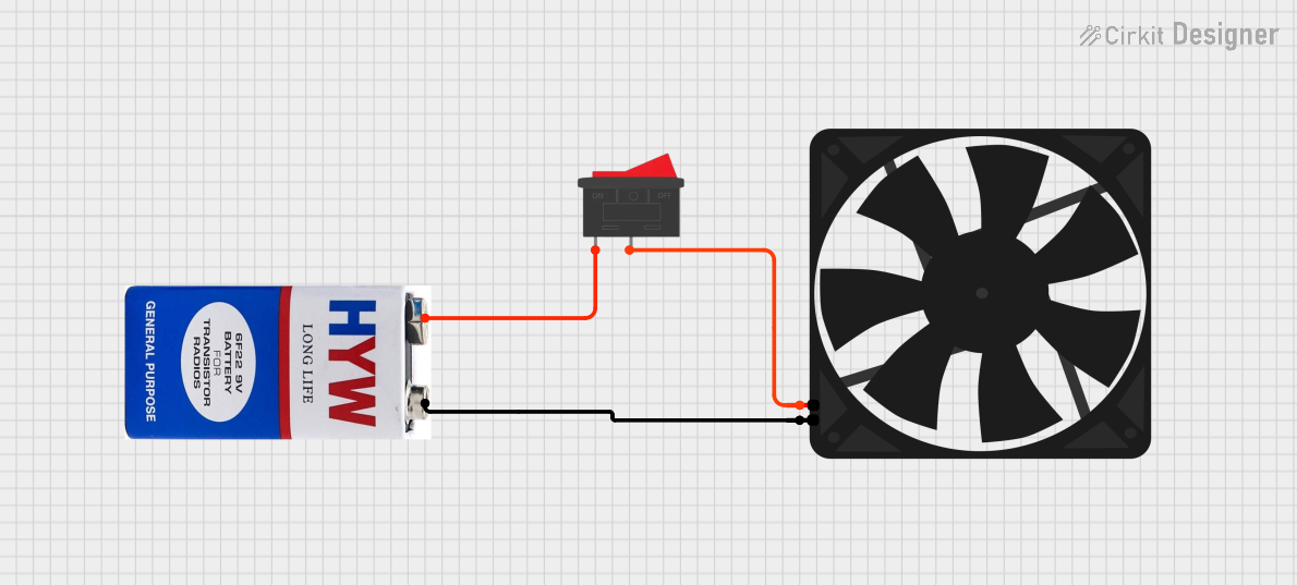
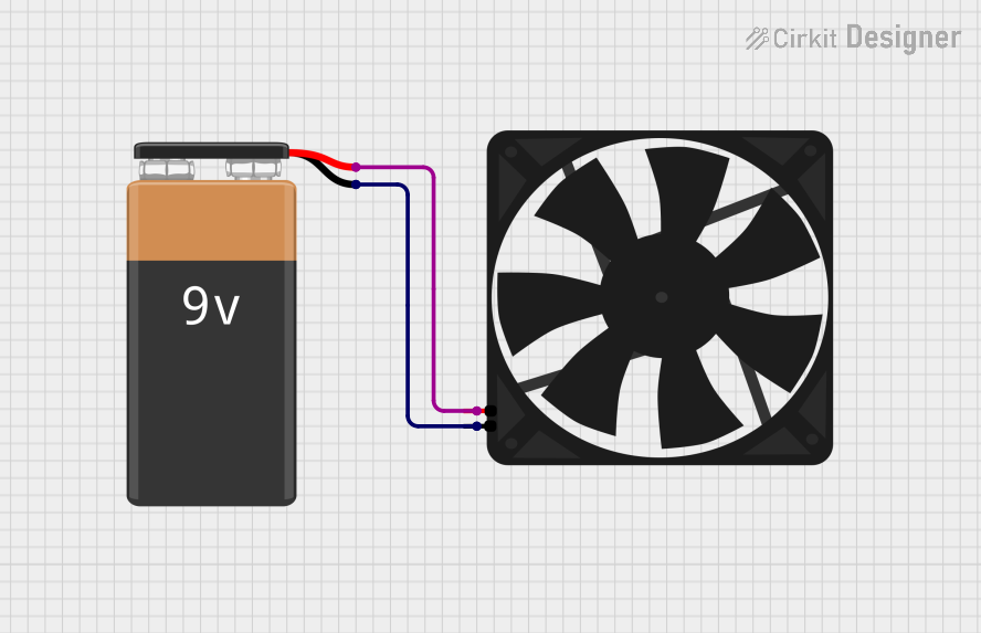
How to Use the Fan in a Circuit
- Power Supply: Ensure the fan is connected to a 12V DC power source. For a 2-pin fan, connect the VCC pin to the positive terminal and the GND pin to the negative terminal of the power supply.
- Speed Monitoring (Optional): If using the 3-pin version, connect the Tach pin to a microcontroller or monitoring circuit to measure the fan's speed.
- Mounting: Secure the fan in place using screws or adhesive mounts. Ensure the airflow direction aligns with the cooling requirements of your system.
- Wiring: Use appropriate gauge wires to handle the current (0.2A) and minimize voltage drops.
Important Considerations and Best Practices
- Voltage Tolerance: Do not exceed the rated 12V DC operating voltage to avoid damaging the fan.
- Airflow Direction: Check the fan's label or housing for arrows indicating airflow direction and blade rotation.
- Noise Reduction: Use rubber mounts or grommets to minimize vibration and noise.
- Maintenance: Periodically clean the fan blades to prevent dust buildup, which can reduce efficiency and increase noise.
- Tachometer Usage: If using the Tach pin, ensure the microcontroller's input pin is configured for digital signal reading.
Example: Connecting the Fan to an Arduino UNO
The following example demonstrates how to connect the GERMANY G7-05001 Fan to an Arduino UNO for speed monitoring using the Tach pin.
Circuit Connections
- Connect the fan's VCC pin to the Arduino's 12V power supply.
- Connect the GND pin to the Arduino's GND.
- Connect the Tach pin to Arduino digital pin 2.
Arduino Code
// Fan Speed Monitoring with Arduino UNO
// Reads the tachometer signal from the fan and calculates RPM

const int tachPin = 2;  // Tachometer pin connected to digital pin 2
volatile int tachCount = 0;  // Counter for tachometer pulses
unsigned long lastTime = 0;  // Time of the last RPM calculation

void setup() {
  pinMode(tachPin, INPUT_PULLUP);  // Set tachPin as input with pull-up resistor
  attachInterrupt(digitalPinToInterrupt(tachPin), countTachPulse, FALLING);
  Serial.begin(9600);  // Initialize serial communication
}

void loop() {
  unsigned long currentTime = millis();
  if (currentTime - lastTime >= 1000) {  // Calculate RPM every second
    int rpm = (tachCount * 60) / 2;  // Convert pulse count to RPM
    Serial.print("Fan Speed: ");
    Serial.print(rpm);
    Serial.println(" RPM");
    tachCount = 0;  // Reset pulse count
    lastTime = currentTime;
  }
}

// Interrupt service routine to count tachometer pulses
void countTachPulse() {
  tachCount++;
}
Troubleshooting and FAQs
Common Issues and Solutions
Fan Not Spinning
- Cause: Insufficient power supply or incorrect wiring.
- Solution: Verify the power supply voltage (12V DC) and check the wiring connections.
Excessive Noise
- Cause: Dust buildup, loose mounting, or worn bearings.
- Solution: Clean the fan blades, tighten the mounting screws, or replace the fan if bearings are worn.
Tachometer Not Working
- Cause: Incorrect connection or incompatible microcontroller pin.
- Solution: Ensure the Tach pin is connected to a digital input pin and verify the microcontroller's configuration.
Overheating Components
- Cause: Insufficient airflow or incorrect fan placement.
- Solution: Reposition the fan to improve airflow and ensure proper ventilation.
FAQs
Q: Can I use the fan with a 5V power supply?
A: No, the fan requires a 12V DC power supply for proper operation.Q: How do I determine the airflow direction?
A: Look for arrows on the fan housing indicating airflow direction and blade rotation.Q: Can I control the fan speed?
A: The G7-05001 does not support PWM speed control. Use a compatible fan controller for speed adjustment.Q: Is the fan waterproof?
A: No, the fan is not waterproof. Avoid exposing it to liquids or high humidity environments.