How to Use dc to dc 3.3 5: Examples, Pinouts, and Specs
Introduction
The DC-DC 3.3V 5V converter is a step-down voltage regulator designed to convert a 5V input to a stable 3.3V output. This component is widely used in electronic circuits to power devices that require a lower voltage, such as microcontrollers, sensors, and communication modules. Its compact size and high efficiency make it an essential component in battery-powered and low-power applications.
Explore Projects Built with dc to dc 3.3 5


Explore Projects Built with dc to dc 3.3 5
Common Applications
- Powering 3.3V microcontrollers (e.g., ESP8266, ESP32)
- Supplying voltage to 3.3V sensors and modules (e.g., GPS, Bluetooth, Wi-Fi)
- Battery-powered devices requiring efficient voltage regulation
- Prototyping and development boards
Technical Specifications
Below are the key technical details of the DC-DC 3.3V 5V converter:
| Parameter | Value |
|---|---|
| Input Voltage Range | 4.5V to 5.5V |
| Output Voltage | 3.3V ± 0.1V |
| Maximum Output Current | 800mA (typical), 1A (peak) |
| Efficiency | Up to 90% |
| Operating Temperature | -40°C to +85°C |
| Dimensions | Varies by model (e.g., 22mm x 17mm) |
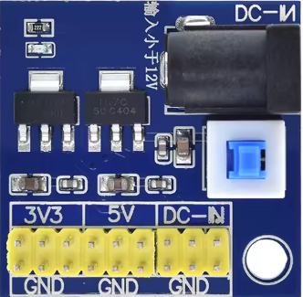
Pin Configuration
The DC-DC converter typically has three pins for easy integration into circuits:
| Pin | Name | Description |
|---|---|---|
| 1 | VIN | Input voltage (4.5V to 5.5V) |
| 2 | GND | Ground connection |
| 3 | VOUT | Regulated 3.3V output voltage |
Usage Instructions
How to Use the Component in a Circuit
- Connect the Input Voltage (VIN):
- Attach the VIN pin to a 5V power source. Ensure the input voltage is within the specified range (4.5V to 5.5V).
- Connect the Ground (GND):
- Connect the GND pin to the ground of your circuit.
- Connect the Output Voltage (VOUT):
- Use the VOUT pin to power your 3.3V device. Ensure the connected device does not exceed the maximum output current.
Important Considerations
- Input Voltage Stability: Ensure the input voltage remains stable and within the specified range to avoid damaging the converter or connected devices.
- Heat Dissipation: For high current loads, consider adding a heatsink or ensuring proper ventilation to prevent overheating.
- Bypass Capacitors: Add a 10µF capacitor across the input and output pins to reduce noise and improve stability.
- Polarity Protection: Double-check the polarity of the connections to avoid damaging the converter.
Example: Using with an Arduino UNO
While the Arduino UNO operates at 5V, you can use the DC-DC converter to power 3.3V peripherals. Below is an example of connecting a 3.3V sensor to the Arduino UNO using the converter:
Circuit Connections
- Connect the VIN pin of the converter to the 5V pin of the Arduino UNO.
- Connect the GND pin of the converter to the GND pin of the Arduino UNO.
- Connect the VOUT pin of the converter to the VCC pin of the 3.3V sensor.
- Connect the GND pin of the sensor to the GND pin of the Arduino UNO.
Example Code
Here is a sample Arduino code to read data from a 3.3V sensor (e.g., a temperature sensor):
// Example code to read data from a 3.3V sensor connected via a DC-DC converter

const int sensorPin = A0; // Analog pin connected to the sensor output

void setup() {
  Serial.begin(9600); // Initialize serial communication at 9600 baud
  pinMode(sensorPin, INPUT); // Set the sensor pin as input
}

void loop() {
  int sensorValue = analogRead(sensorPin); // Read the sensor value
  float voltage = sensorValue * (3.3 / 1023.0); // Convert to voltage (3.3V reference)

  // Print the sensor value and voltage to the Serial Monitor
  Serial.print("Sensor Value: ");
  Serial.print(sensorValue);
  Serial.print(" | Voltage: ");
  Serial.println(voltage);

  delay(1000); // Wait for 1 second before the next reading
}
Troubleshooting and FAQs
Common Issues and Solutions
No Output Voltage:
- Cause: Incorrect wiring or insufficient input voltage.
- Solution: Verify the connections and ensure the input voltage is within the specified range.
Overheating:
- Cause: Excessive current draw or poor ventilation.
- Solution: Reduce the load current or add a heatsink to the converter.
Output Voltage Fluctuations:
- Cause: Noise or unstable input voltage.
- Solution: Add bypass capacitors (e.g., 10µF) across the input and output pins.
Device Not Powering On:
- Cause: Polarity mismatch or damaged converter.
- Solution: Check the polarity of the connections and replace the converter if necessary.
FAQs
Q: Can I use this converter with a 3.7V Li-ion battery?
A: No, the input voltage must be at least 4.5V. Consider using a boost converter for lower input voltages.
Q: Is the output voltage adjustable?
A: No, this converter provides a fixed 3.3V output.
Q: Can I use this converter to power multiple devices?
A: Yes, as long as the total current draw does not exceed the maximum output current (800mA typical, 1A peak).
Q: Does the converter have built-in short-circuit protection?
A: Some models may include short-circuit protection, but it is recommended to check the specific datasheet for your converter.
This concludes the documentation for the DC-DC 3.3V 5V converter.