How to Use Adafruit PDM Mic: Examples, Pinouts, and Specs
Introduction
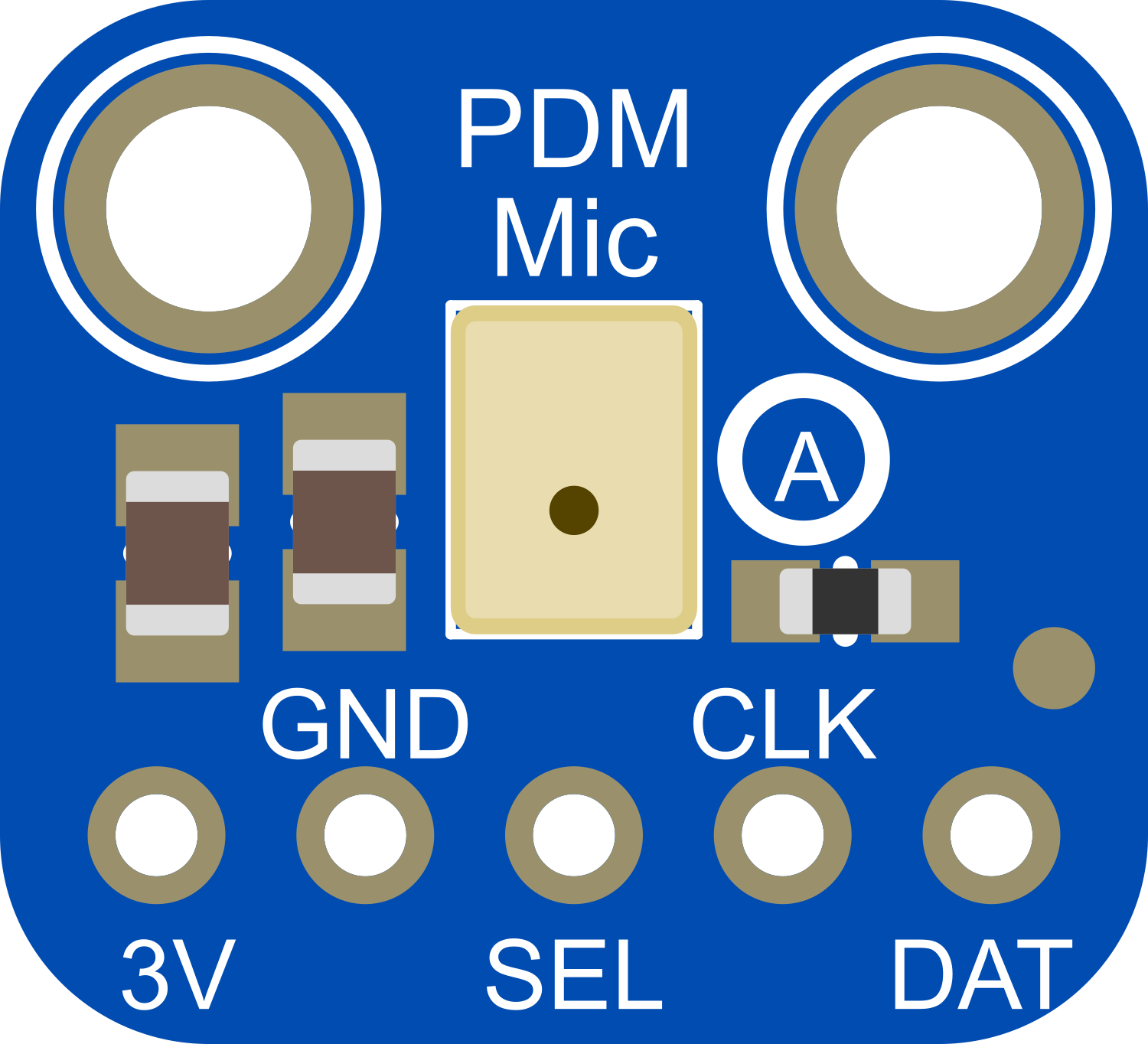
The Adafruit PDM Mic is a high-quality digital microphone module that captures audio using Pulse Density Modulation (PDM). It is designed for use with microcontrollers, such as the Arduino UNO, that support PDM input. This microphone is ideal for applications requiring sound input, such as voice recognition, audio recording, and environmental sound analysis.
Explore Projects Built with Adafruit PDM Mic
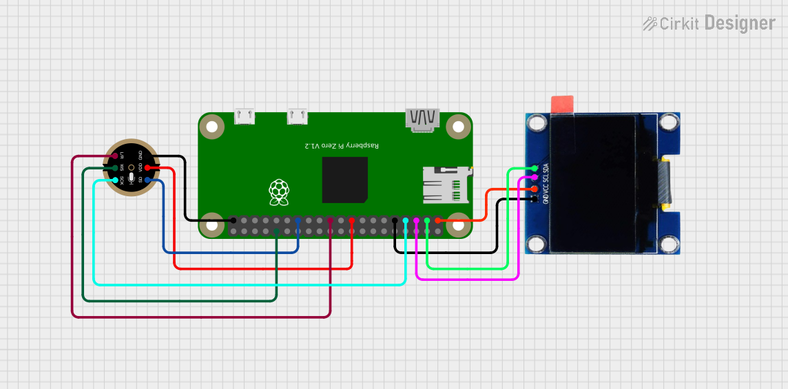
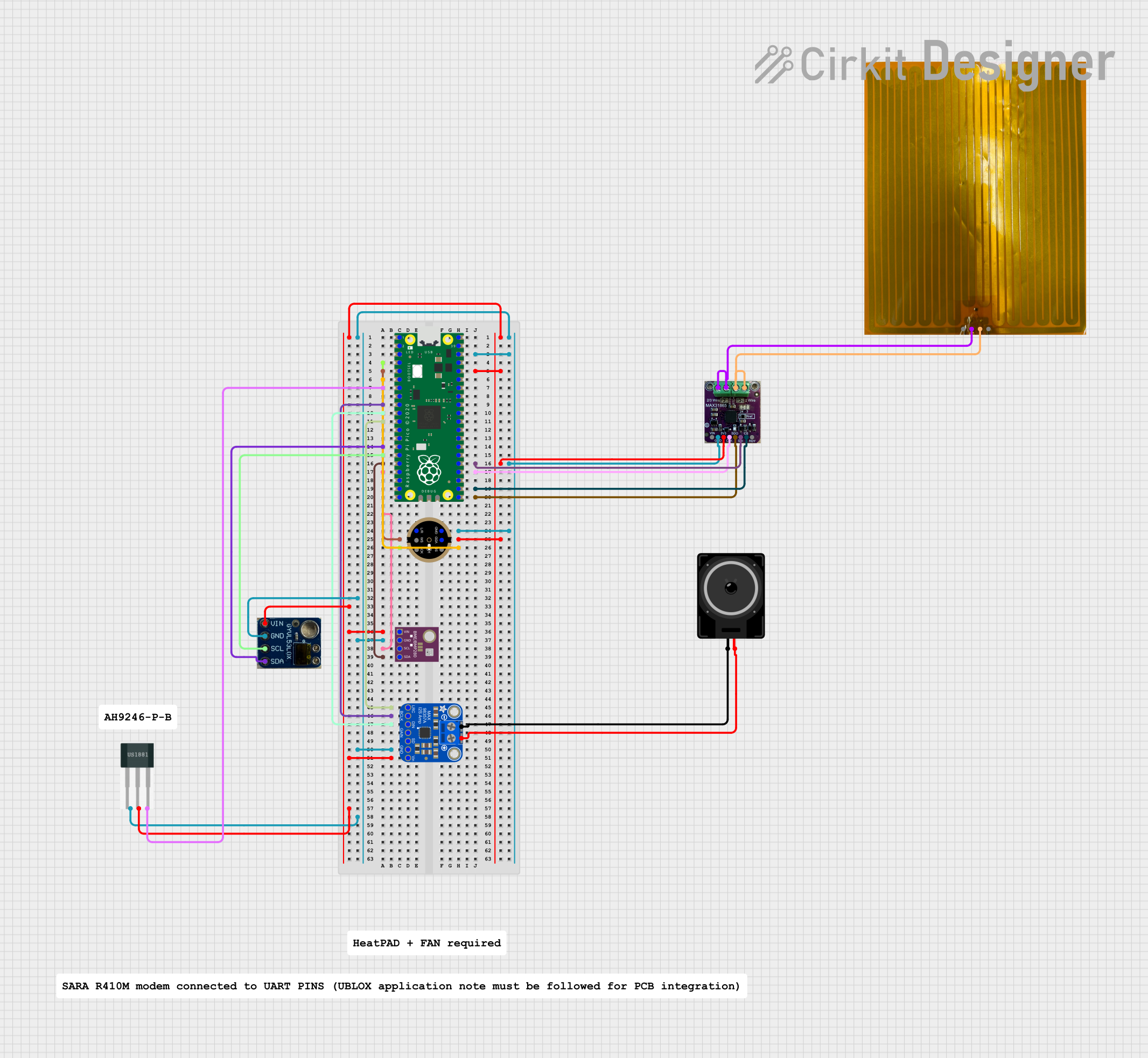
Explore Projects Built with Adafruit PDM Mic
Technical Specifications
Key Technical Details
- Microphone Type: Digital PDM MEMS
- Operating Voltage: 3.3V
- Current Consumption: 650 µA (typical)
- Sensitivity: -26 dBFS (typical)
- Signal-to-Noise Ratio (SNR): 65 dB (typical)
- Acoustic Overload Point: 120 dB SPL (Sound Pressure Level)
- Frequency Response: 20 Hz to 20 kHz
- Interface: PDM (1-bit Pulse Density Modulation)
Pin Configuration and Descriptions
| Pin Number | Name | Description |
|---|---|---|
| 1 | SEL | Select pin for left or right channel (tied to GND or VCC) |
| 2 | GND | Ground connection |
| 3 | 3V | Power supply (3.3V) |
| 4 | CLK | Clock input for PDM data (1 - 3.2 MHz) |
| 5 | DAT | PDM data output |
Usage Instructions
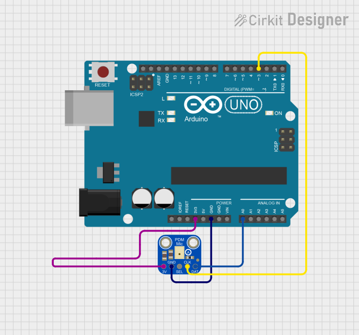
Integration with a Circuit
- Power Supply: Connect the 3V pin to a 3.3V power source and the GND pin to the ground.
- Clock Input: Connect the CLK pin to a digital output capable of generating a clock signal.
- Data Output: Connect the DAT pin to a microcontroller pin capable of receiving PDM data.
- Channel Selection: Optionally, connect the SEL pin to GND for the left channel or VCC for the right channel.
Best Practices
- Use a clean and stable power supply to minimize noise.
- Keep the microphone away from sources of mechanical vibration.
- Avoid running the microphone wires close to high-current traces to prevent electromagnetic interference.
- Ensure that the microcontroller's firmware supports PDM decoding.
Example Code for Arduino UNO
#include <PDM.h>

// Define the PDM pins
const int clkPin = 2; // Clock pin connected to the microphone CLK
const int dataPin = 3; // Data pin connected to the microphone DAT

// Buffer to store PDM data
short buffer[512];

void onPDMdata() {
  // Callback function called when PDM data is available
  int bytesAvailable = PDM.available();
  PDM.read(buffer, bytesAvailable);
  // Process the PDM data in 'buffer'
}

void setup() {
  // Configure the CLK and DAT pins
  pinMode(clkPin, OUTPUT);
  pinMode(dataPin, INPUT);

  // Begin PDM with a 1MHz clock
  PDM.begin(1, 16000);
  PDM.onReceive(onPDMdata);
  PDM.setGain(20);
}

void loop() {
  // Main loop does nothing; PDM data is handled in onPDMdata()
}
Troubleshooting and FAQs
Common Issues
- No Audio Data: Ensure that the microphone is correctly powered and that the CLK and DAT pins are properly connected.
- Noisy Audio Signal: Check for a stable power supply and minimize interference from other electronic components.
- Low Volume: Adjust the gain settings in the code or check the microphone's orientation and placement.
FAQs
Q: Can the Adafruit PDM Mic be used with a 5V microcontroller? A: The microphone operates at 3.3V. A level shifter is recommended when interfacing with 5V logic.
Q: How do I change the microphone's gain?
A: The gain can be adjusted in the software using the PDM.setGain() function.
Q: What is the maximum clock frequency for the PDM Mic? A: The maximum clock frequency is 3.2 MHz.
Q: Can I use this microphone for stereo audio capture? A: Yes, by using two microphones and setting one to the left and the other to the right channel using the SEL pin.
For further assistance, consult the Adafruit PDM Mic datasheet and the microcontroller's PDM interface documentation.