
How to Use BQ24022 (DRC-10): Examples, Pinouts, and Specs
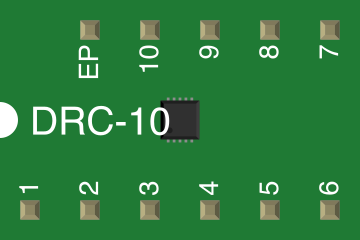
 Design with BQ24022 (DRC-10) in Cirkit Designer
Introduction
The BQ24022 is a highly integrated Li-Ion battery charger with power path management, designed and manufactured by Texas Instruments. This component is ideal for portable applications requiring efficient battery charging and seamless power management. It features a built-in high-efficiency switching regulator, supports both USB and AC adapter inputs, and includes advanced safety features such as thermal regulation, overvoltage protection, and battery temperature monitoring.
Explore Projects Built with BQ24022 (DRC-10)
 Open Project in Cirkit Designer
 Open Project in Cirkit Designer
 Open Project in Cirkit Designer
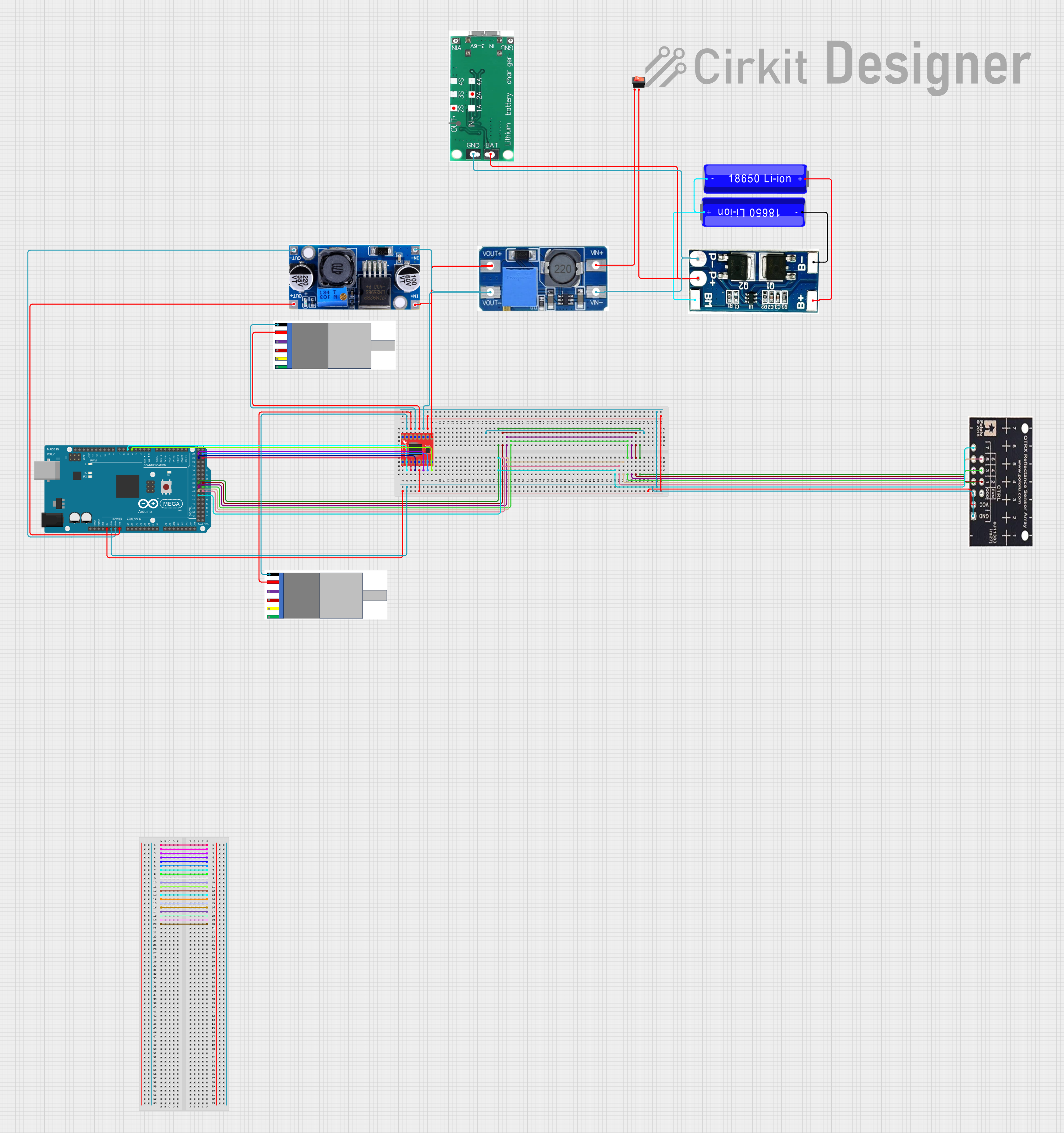 Open Project in Cirkit Designer
Explore Projects Built with BQ24022 (DRC-10)
Open Project in Cirkit DesignerOpen Project in Cirkit DesignerOpen Project in Cirkit DesignerOpen Project in Cirkit DesignerCommon Applications
- Smartphones and tablets
- Wearable devices
- Portable medical equipment
- Power banks
- Handheld gaming devices
Technical Specifications
Key Technical Details
| Parameter | Value |
|---|---|
| Input Voltage Range | 4.35 V to 16 V |
| Charge Voltage | 4.2 V (typical) |
| Charge Current | Programmable up to 1.5 A |
| Input Current Limit | Programmable up to 1.5 A |
| Efficiency | Up to 95% |
| Operating Temperature Range | -40°C to +125°C |
| Package Type | DRC-10 (3 mm × 3 mm VSON) |
| Safety Features | Thermal regulation, overvoltage protection, |
| battery temperature monitoring, and timers |
Pin Configuration and Descriptions
The BQ24022 is available in a DRC-10 package with the following pinout:
| Pin No. | Pin Name | Type | Description |
|---|---|---|---|
| 1 | IN | Power | Input power supply (USB or AC adapter). |
| 2 | OUT | Power | System output voltage. Connect to the load. |
| 3 | BAT | Power | Battery connection. Connect to the positive terminal of the Li-Ion battery. |
| 4 | ISET | Analog | Charge current programming pin. Connect a resistor to set the charge current. |
| 5 | TS | Analog | Battery temperature sensing input. Connect to an NTC thermistor. |
| 6 | CE | Digital In | Charge enable pin. Active low to enable charging. |
| 7 | STAT1 | Digital Out | Open-drain status output 1. Indicates charging status. |
| 8 | STAT2 | Digital Out | Open-drain status output 2. Indicates charging status. |
| 9 | PG | Digital Out | Power good indicator. Active low when input power is valid. |
| 10 | GND | Ground | Ground connection. |
Usage Instructions
How to Use the BQ24022 in a Circuit
- Power Input: Connect the input power source (USB or AC adapter) to the IN pin. Ensure the input voltage is within the range of 4.35 V to 16 V.
- Battery Connection: Connect the positive terminal of the Li-Ion battery to the BAT pin and the negative terminal to GND.
- Load Connection: Connect the system load to the OUT pin. The BQ24022 will manage power distribution between the battery and the load.
- Charge Current Programming: Use a resistor on the ISET pin to set the desired charge current. Refer to the datasheet for the resistor value calculation.
- Battery Temperature Monitoring: Connect an NTC thermistor to the TS pin for battery temperature sensing. This ensures safe charging under various temperature conditions.
- Status Indicators: Use the STAT1 and STAT2 pins to monitor the charging status. These pins can drive LEDs for visual indication.
- Power Good Indicator: Use the PG pin to monitor the validity of the input power source.
Important Considerations and Best Practices
- Ensure proper decoupling capacitors are placed near the IN and OUT pins to minimize noise and improve stability.
- Use a low-ESR capacitor on the BAT pin to stabilize the battery voltage.
- Avoid exceeding the maximum input voltage (16 V) to prevent damage to the device.
- If not using the TS pin, connect it to a fixed voltage as specified in the datasheet to disable temperature monitoring.
- Ensure proper thermal management by placing the device on a PCB with adequate copper area for heat dissipation.
Example: Using BQ24022 with Arduino UNO
The BQ24022 can be used to power an Arduino UNO while charging a Li-Ion battery. Below is an example code to monitor the charging status using the STAT1 and STAT2 pins.
// Arduino UNO example to monitor BQ24022 charging status

const int STAT1_PIN = 2; // Connect STAT1 to digital pin 2
const int STAT2_PIN = 3; // Connect STAT2 to digital pin 3

void setup() {
  pinMode(STAT1_PIN, INPUT); // Set STAT1 as input
  pinMode(STAT2_PIN, INPUT); // Set STAT2 as input
  Serial.begin(9600);        // Initialize serial communication
}

void loop() {
  int stat1 = digitalRead(STAT1_PIN); // Read STAT1 pin
  int stat2 = digitalRead(STAT2_PIN); // Read STAT2 pin

  if (stat1 == LOW && stat2 == HIGH) {
    Serial.println("Charging in progress...");
  } else if (stat1 == HIGH && stat2 == LOW) {
    Serial.println("Charge complete.");
  } else if (stat1 == HIGH && stat2 == HIGH) {
    Serial.println("No battery connected or fault condition.");
  } else {
    Serial.println("Unknown status.");
  }

  delay(1000); // Wait for 1 second before checking again
}
Troubleshooting and FAQs
Common Issues and Solutions
Device Overheating
- Cause: Insufficient thermal dissipation.
- Solution: Increase the copper area on the PCB around the device for better heat dissipation.
Battery Not Charging
- Cause: Incorrect resistor value on the ISET pin.
- Solution: Verify the resistor value and ensure it matches the desired charge current.
Power Good Indicator Not Active
- Cause: Input voltage is out of range or unstable.
- Solution: Check the input power source and ensure it is within the specified range (4.35 V to 16 V).
Fault Condition Indicated
- Cause: Battery temperature out of range or overvoltage condition.
- Solution: Verify the connection to the TS pin and ensure the battery voltage is within the safe range.
FAQs
Q1: Can the BQ24022 charge other types of batteries?
A1: No, the BQ24022 is specifically designed for single-cell Li-Ion or Li-Polymer batteries.
Q2: What happens if the input power is removed?
A2: The BQ24022 seamlessly switches to battery power to supply the load via the OUT pin.
Q3: Can I disable charging while still powering the load?
A3: Yes, you can disable charging by pulling the CE pin high while the load remains powered through the OUT pin.
Q4: How do I calculate the resistor value for the ISET pin?
A4: Refer to the formula in the datasheet: R_ISET = 1000 / I_CHG, where I_CHG is the desired charge current in amperes.