How to Use Arduino 33 Nano IoT: Examples, Pinouts, and Specs
Introduction
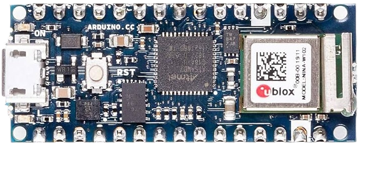
The Arduino Nano 33 IoT is a compact microcontroller board based on the ARM Cortex-M4 architecture. It is specifically designed for Internet of Things (IoT) applications, featuring built-in Wi-Fi and Bluetooth connectivity. This board is ideal for creating connected devices, enabling seamless communication with cloud services, mobile devices, and other IoT systems. Its small form factor makes it suitable for projects with space constraints, while its powerful processing capabilities allow for advanced data processing and control.
Explore Projects Built with Arduino 33 Nano IoT
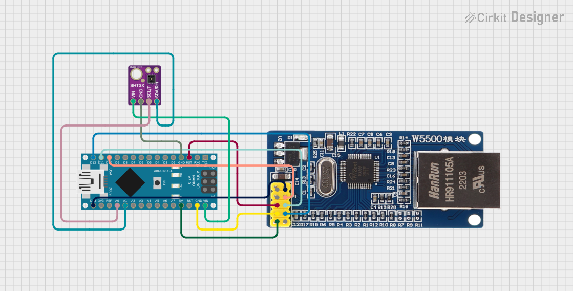
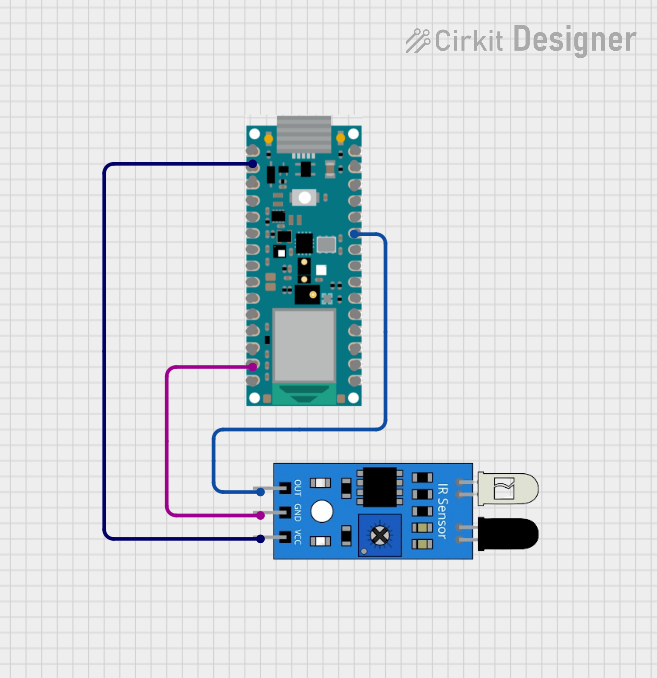
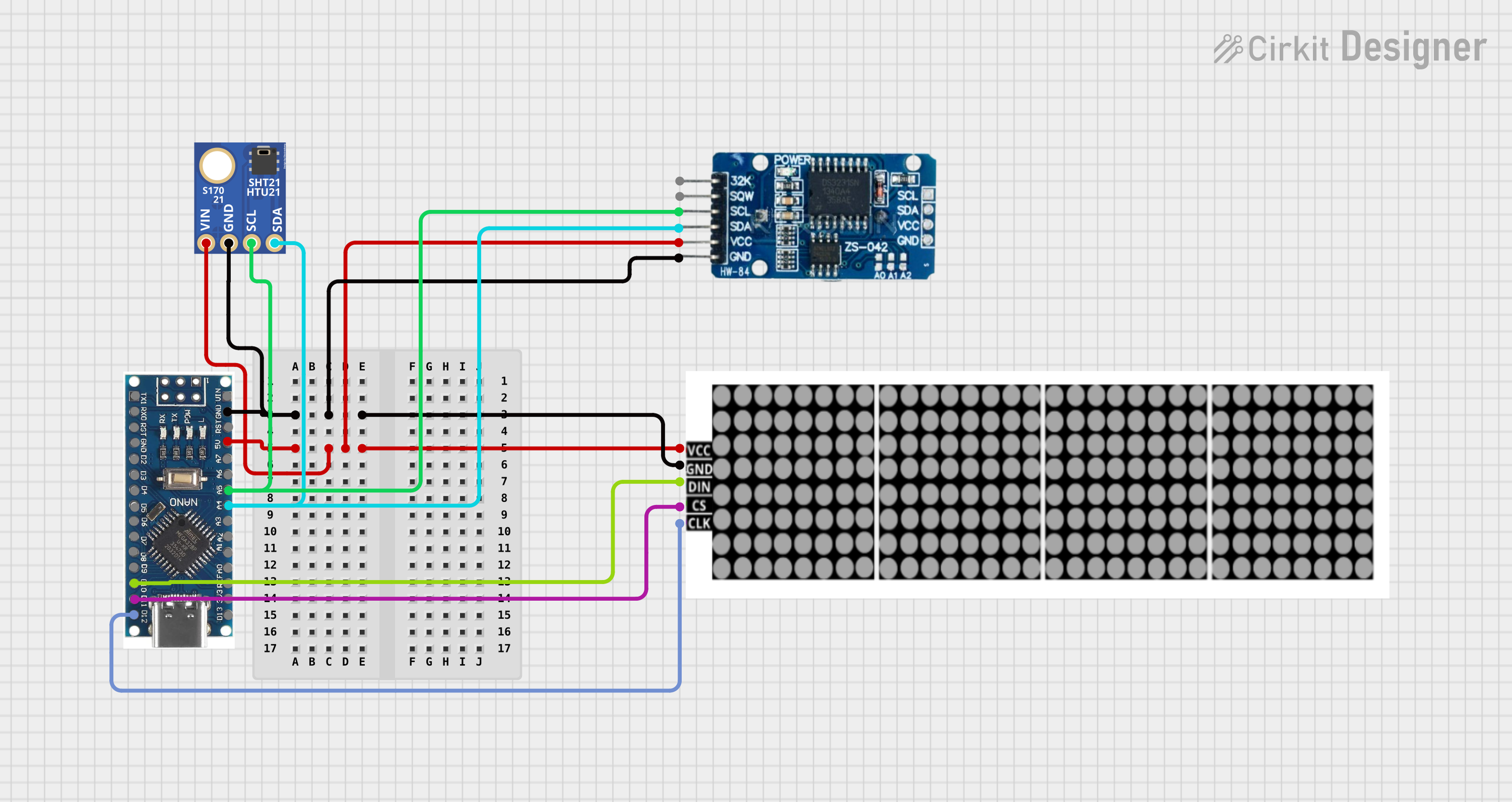
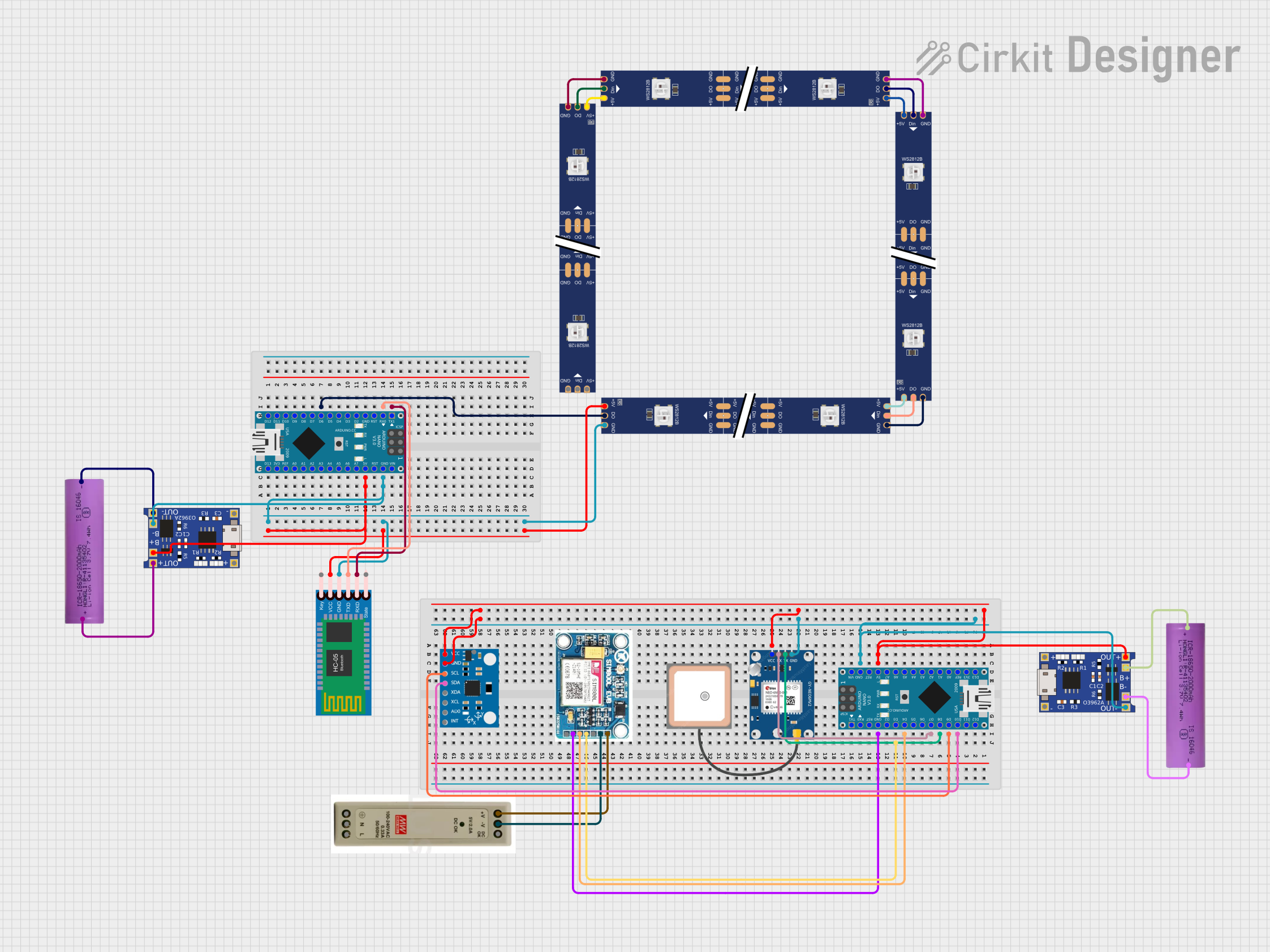
Explore Projects Built with Arduino 33 Nano IoT
Common Applications and Use Cases
- Smart home devices (e.g., connected lights, thermostats, and sensors)
- Wearable technology
- Industrial IoT systems
- Environmental monitoring
- Remote control and automation
- Prototyping IoT solutions
Technical Specifications
The Arduino Nano 33 IoT is packed with features that make it versatile and powerful for IoT applications. Below are its key technical details:
Key Technical Details
- Microcontroller: SAMD21 Cortex-M0+ 32-bit ARM processor
- Connectivity: Wi-Fi (802.11 b/g/n), Bluetooth 4.2 (BLE)
- Operating Voltage: 3.3V
- Input Voltage (VIN): 5-21V
- Digital I/O Pins: 14 (12 PWM outputs)
- Analog Input Pins: 8
- Analog Output Pins: 1 (DAC)
- Flash Memory: 256 KB
- SRAM: 32 KB
- Clock Speed: 48 MHz
- Dimensions: 45 x 18 mm
- Weight: 5 g
Pin Configuration and Descriptions
The Arduino Nano 33 IoT has a total of 30 pins. Below is the pinout and description:
| Pin | Type | Description |
|---|---|---|
| VIN | Power Input | External power input (5-21V). |
| 3.3V | Power Output | Regulated 3.3V output. |
| GND | Ground | Ground connection. |
| A0-A7 | Analog Input | Analog input pins (12-bit ADC). |
| D0-D13 | Digital I/O | Digital input/output pins (PWM available on D2-D13). |
| TX (D1) | UART TX | Transmit pin for serial communication. |
| RX (D0) | UART RX | Receive pin for serial communication. |
| SDA | I2C Data | Data line for I2C communication. |
| SCL | I2C Clock | Clock line for I2C communication. |
| MOSI | SPI Data Out | Master Out Slave In for SPI communication. |
| MISO | SPI Data In | Master In Slave Out for SPI communication. |
| SCK | SPI Clock | Clock line for SPI communication. |
| RST | Reset | Resets the microcontroller. |
| AREF | Analog Ref. | Reference voltage for analog inputs. |
| LED_BUILTIN | Digital Output | Onboard LED connected to D13. |
Usage Instructions
The Arduino Nano 33 IoT is easy to use and can be programmed using the Arduino IDE. Below are the steps to get started and some important considerations.
How to Use the Arduino Nano 33 IoT in a Circuit
- Power the Board: Connect the board to your computer via a USB cable or use an external power source (5-21V via VIN pin).
- Install the Arduino IDE: Download and install the latest version of the Arduino IDE from the official website.
- Install the Board Package:
- Open the Arduino IDE.
- Go to
Tools > Board > Boards Manager. - Search for "Arduino SAMD Boards" and install the package.
- Select the Board and Port:
- Go to
Tools > Boardand select "Arduino Nano 33 IoT". - Go to
Tools > Portand select the port to which the board is connected.
- Go to
- Write and Upload Code:
- Write your code in the Arduino IDE.
- Click the upload button to program the board.
Example Code: Connecting to Wi-Fi
The following example demonstrates how to connect the Arduino Nano 33 IoT to a Wi-Fi network.
#include <WiFiNINA.h> // Include the WiFiNINA library

// Replace with your network credentials
const char* ssid = "Your_SSID";       // Your Wi-Fi network name
const char* password = "Your_Password"; // Your Wi-Fi network password

void setup() {
  Serial.begin(9600); // Start serial communication at 9600 baud
  while (!Serial);    // Wait for the serial monitor to open

  Serial.println("Connecting to Wi-Fi...");

  // Attempt to connect to Wi-Fi
  if (WiFi.begin(ssid, password) != WL_CONNECTED) {
    Serial.println("Failed to connect to Wi-Fi");
    while (true); // Halt execution if connection fails
  }

  Serial.println("Connected to Wi-Fi!");
  Serial.print("IP Address: ");
  Serial.println(WiFi.localIP()); // Print the device's IP address
}

void loop() {
  // Add your main code here
}
Important Considerations and Best Practices
- Voltage Levels: The Arduino Nano 33 IoT operates at 3.3V. Ensure that any external components connected to the board are compatible with 3.3V logic levels.
- Wi-Fi Antenna: Avoid placing the board in a metal enclosure or near other electronic components that may interfere with the onboard Wi-Fi antenna.
- Firmware Updates: Keep the Wi-FiNINA firmware up to date for optimal performance. Use the Firmware Updater tool in the Arduino IDE to update the firmware.
Troubleshooting and FAQs
Common Issues and Solutions
The board is not detected by the Arduino IDE:
- Ensure the correct USB cable is used (some cables are power-only and do not support data transfer).
- Check that the correct board and port are selected in the Arduino IDE.
- Try reinstalling the Arduino SAMD Boards package.
Wi-Fi connection fails:
- Double-check the SSID and password for your Wi-Fi network.
- Ensure the Wi-Fi network is 2.4 GHz, as the board does not support 5 GHz networks.
- Update the Wi-FiNINA library and firmware.
Code upload fails:
- Press the reset button on the board twice to enter bootloader mode, then try uploading the code again.
- Check for conflicting drivers or software on your computer.
FAQs
Can I use the Arduino Nano 33 IoT with 5V sensors? No, the board operates at 3.3V. Use a level shifter to interface with 5V sensors.
How do I update the Wi-FiNINA firmware? Open the Arduino IDE, go to
Tools > WiFi101/WiFiNINA Firmware Updater, and follow the instructions.What is the range of the onboard Bluetooth? The Bluetooth range is approximately 10 meters, depending on environmental factors.
By following this documentation, you can effectively use the Arduino Nano 33 IoT for your IoT projects.