How to Use motor and wheels: Examples, Pinouts, and Specs
Introduction
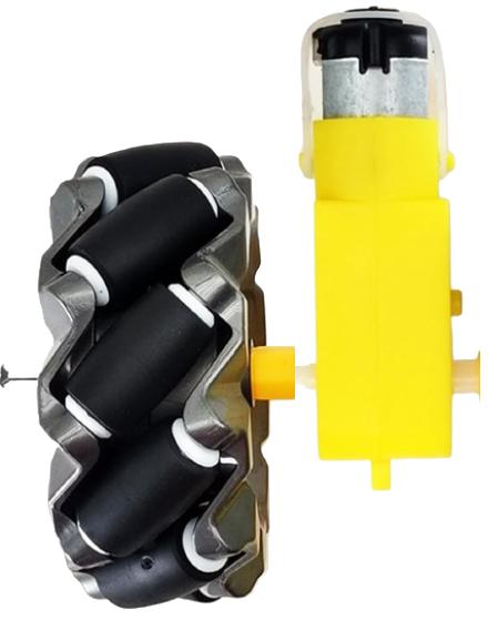
The motor and wheels assembly is a fundamental component in robotics and automation systems. It consists of a motor (typically a DC motor or stepper motor) connected to wheels, enabling movement and mobility for robots, vehicles, or other mechanical systems. This component is widely used in applications such as robotic cars, conveyor systems, and automated guided vehicles (AGVs).
Common applications and use cases include:
- Robotic platforms for education and research
- Remote-controlled vehicles
- Line-following and obstacle-avoiding robots
- Automated delivery systems
Explore Projects Built with motor and wheels

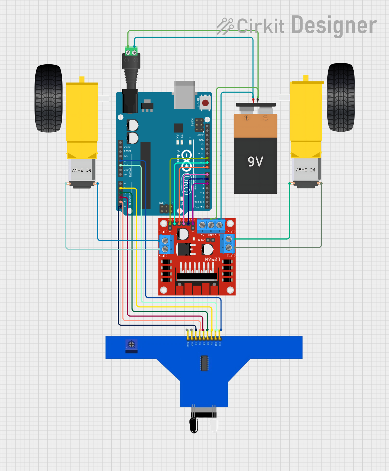
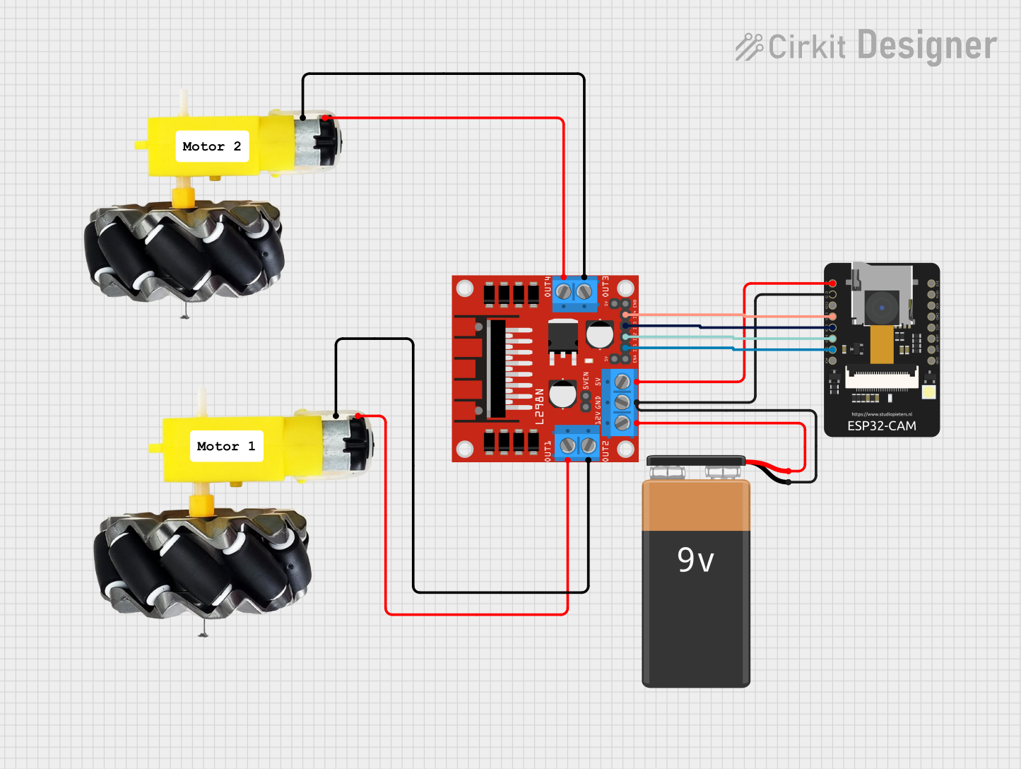
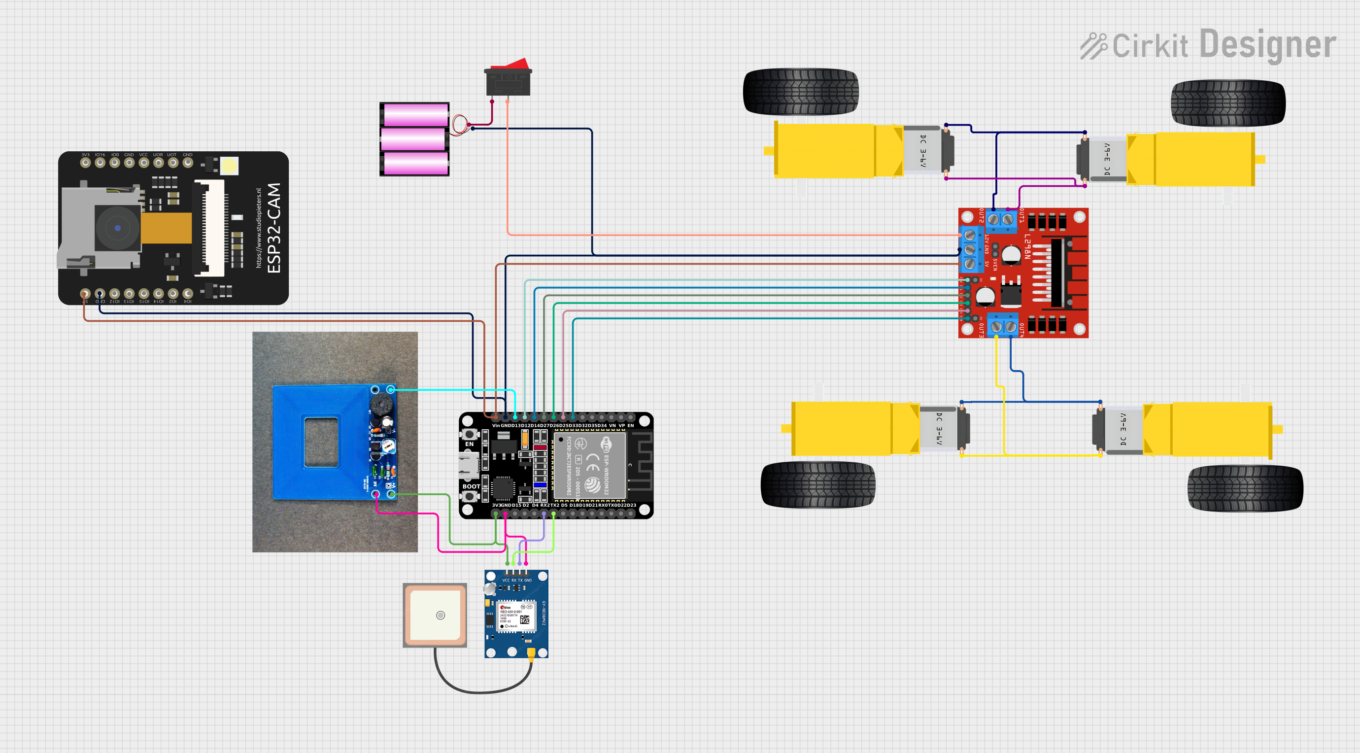
Explore Projects Built with motor and wheels
Technical Specifications
The motor and wheels assembly can vary depending on the specific model and manufacturer. Below are general specifications for a typical DC motor and wheel setup:
Motor Specifications
| Parameter | Value |
|---|---|
| Operating Voltage | 3V to 12V |
| Rated Current | 100mA to 1A (depending on load) |
| Stall Current | 1.5A to 2A |
| Torque | 0.5 kg·cm to 3 kg·cm |
| Speed | 100 RPM to 300 RPM |
| Motor Type | Brushed DC Motor |
Wheel Specifications
| Parameter | Value |
|---|---|
| Diameter | 65mm to 100mm |
| Material | Rubber or plastic |
| Mounting Type | Direct fit or screw mount |
| Tread Type | Smooth or grooved |
Pin Configuration (for DC Motor)
| Pin Name | Description |
|---|---|
| V+ (Positive Terminal) | Connects to the positive supply voltage |
| V- (Negative Terminal) | Connects to the ground or negative supply voltage |
Usage Instructions
How to Use the Component in a Circuit
- Power Supply: Connect the motor terminals to a suitable power source. Ensure the voltage and current ratings match the motor's specifications.
- Motor Driver: Use a motor driver (e.g., L298N or L293D) to control the motor. Directly connecting the motor to a microcontroller is not recommended due to high current requirements.
- Wiring: Connect the motor driver to the microcontroller and power supply. The motor driver will act as an interface between the microcontroller and the motor.
- Wheel Attachment: Secure the wheels to the motor shaft using screws or a direct-fit mechanism.
Important Considerations and Best Practices
- Current Limiting: Use a motor driver with built-in current limiting to protect the motor and power supply.
- Heat Dissipation: Ensure proper ventilation or heat sinks for the motor driver to prevent overheating.
- Load Balancing: Avoid overloading the motor, as this can cause excessive current draw and damage the motor.
- Power Supply: Use a stable and regulated power supply to ensure consistent performance.
Example: Controlling a Motor and Wheels with Arduino UNO
Below is an example of controlling a motor and wheels using an Arduino UNO and an L298N motor driver:
// Include necessary libraries (if any)
// Define motor control pins
const int ENA = 9;  // Enable pin for motor A
const int IN1 = 8;  // Input 1 for motor A
const int IN2 = 7;  // Input 2 for motor A

void setup() {
  // Set motor control pins as outputs
  pinMode(ENA, OUTPUT);
  pinMode(IN1, OUTPUT);
  pinMode(IN2, OUTPUT);

  // Initialize motor in stopped state
  digitalWrite(IN1, LOW);
  digitalWrite(IN2, LOW);
  analogWrite(ENA, 0);  // Set speed to 0
}

void loop() {
  // Example: Move forward
  digitalWrite(IN1, HIGH);  // Set IN1 high
  digitalWrite(IN2, LOW);   // Set IN2 low
  analogWrite(ENA, 150);    // Set speed (0-255)

  delay(2000);  // Move forward for 2 seconds

  // Example: Stop
  digitalWrite(IN1, LOW);
  digitalWrite(IN2, LOW);
  analogWrite(ENA, 0);

  delay(1000);  // Stop for 1 second
}
Notes:
- Adjust the
ENAvalue to control the motor speed. - Reverse the
IN1andIN2states to change the motor's direction.
Troubleshooting and FAQs
Common Issues
Motor Not Spinning:
- Check the power supply voltage and current.
- Verify the motor driver connections and ensure the enable pin is active.
- Ensure the motor is not overloaded or stalled.
Motor Overheating:
- Reduce the load on the motor.
- Check for proper ventilation and heat dissipation.
Inconsistent Speed:
- Use a regulated power supply to avoid voltage fluctuations.
- Check for loose connections or damaged wires.
Arduino Not Controlling the Motor:
- Verify the motor driver connections to the Arduino.
- Ensure the correct pins are defined in the code.
- Check the motor driver enable pin and ensure it is receiving a signal.
FAQs
Q: Can I connect the motor directly to the Arduino?
A: No, the Arduino cannot supply the high current required by the motor. Always use a motor driver.
Q: How do I reverse the motor's direction?
A: Swap the IN1 and IN2 states in the code or reverse the motor's polarity.
Q: What type of wheels should I use?
A: Choose wheels based on your application. For smooth surfaces, use rubber wheels with good traction. For rough terrain, use grooved or larger-diameter wheels.
Q: Can I use a battery to power the motor?
A: Yes, but ensure the battery can supply sufficient voltage and current for the motor and driver.
By following this documentation, you can effectively integrate and troubleshoot a motor and wheels assembly in your projects.