How to Use INMP441: Examples, Pinouts, and Specs
Introduction
The INMP441 is a low-power, high-performance MEMS (Micro-Electro-Mechanical Systems) microphone with a digital I2S (Inter-IC Sound) output. It is designed to deliver high-quality audio capture in a compact form factor, making it ideal for modern audio applications. The microphone's digital output eliminates the need for an external ADC (Analog-to-Digital Converter), simplifying integration into digital systems.
Explore Projects Built with INMP441
Explore Projects Built with INMP441
Common Applications and Use Cases
- Smartphones and tablets
- Voice-activated devices (e.g., smart speakers, virtual assistants)
- Audio recording systems
- IoT devices with voice recognition
- Wearable devices
Technical Specifications
The INMP441 is optimized for low power consumption and high audio fidelity. Below are its key technical specifications:
| Parameter | Value |
|---|---|
| Supply Voltage (VDD) | 1.8V to 3.3V |
| Current Consumption | 1.4 mA (typical) |
| Signal-to-Noise Ratio (SNR) | 61 dB |
| Acoustic Overload Point | 120 dB SPL |
| Frequency Response | 60 Hz to 15 kHz |
| Output Format | I2S (24-bit, 2's complement) |
| Sensitivity | -26 dBFS ±1 dB |
| Operating Temperature Range | -40°C to +85°C |
| Dimensions | 3.5 mm × 2.65 mm × 0.98 mm |
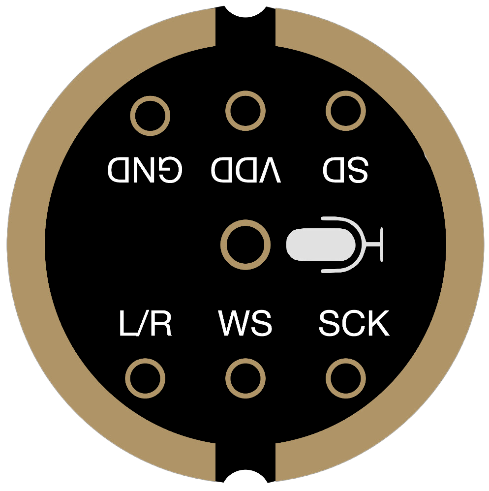
Pin Configuration and Descriptions
The INMP441 has a total of 7 pins. Below is the pinout and description:
| Pin Name | Pin Number | Description |
|---|---|---|
| VDD | 1 | Power supply input (1.8V to 3.3V). |
| GND | 2 | Ground connection. |
| WS | 3 | Word Select (I2S clock signal for left/right channel selection). |
| SCK | 4 | Serial Clock (I2S clock signal for data synchronization). |
| SD | 5 | Serial Data (I2S digital audio data output). |
| L/R | 6 | Left/Right channel select. Connect to GND for left channel or VDD for right. |
| NC | 7 | No connection. Leave unconnected or grounded. |
Usage Instructions
How to Use the INMP441 in a Circuit
- Power Supply: Connect the VDD pin to a regulated power supply (1.8V to 3.3V) and the GND pin to the ground.
- I2S Interface: Connect the WS, SCK, and SD pins to the corresponding I2S pins of your microcontroller or audio processor.
- Channel Selection: Use the L/R pin to configure the microphone as a left or right channel:
- Connect to GND for the left channel.
- Connect to VDD for the right channel.
- Bypass Capacitor: Place a 0.1 µF ceramic capacitor close to the VDD pin to stabilize the power supply.
Important Considerations and Best Practices
- Ensure the I2S clock signals (WS and SCK) are properly configured to match the microphone's output format.
- Avoid placing the microphone near high-frequency noise sources to maintain audio quality.
- Use proper grounding techniques to minimize noise and interference.
- The INMP441 is sensitive to mechanical stress; handle it carefully during soldering and assembly.
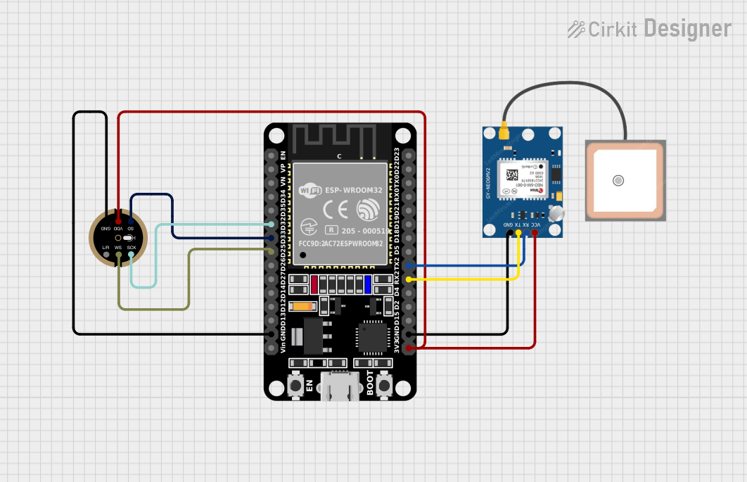
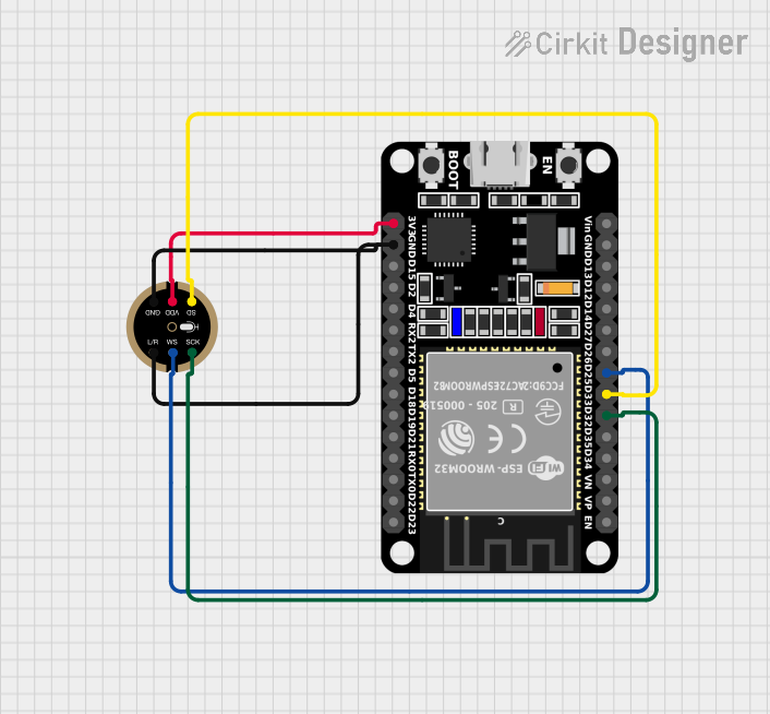
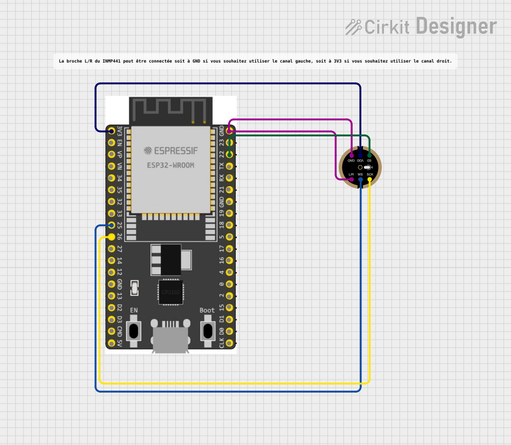
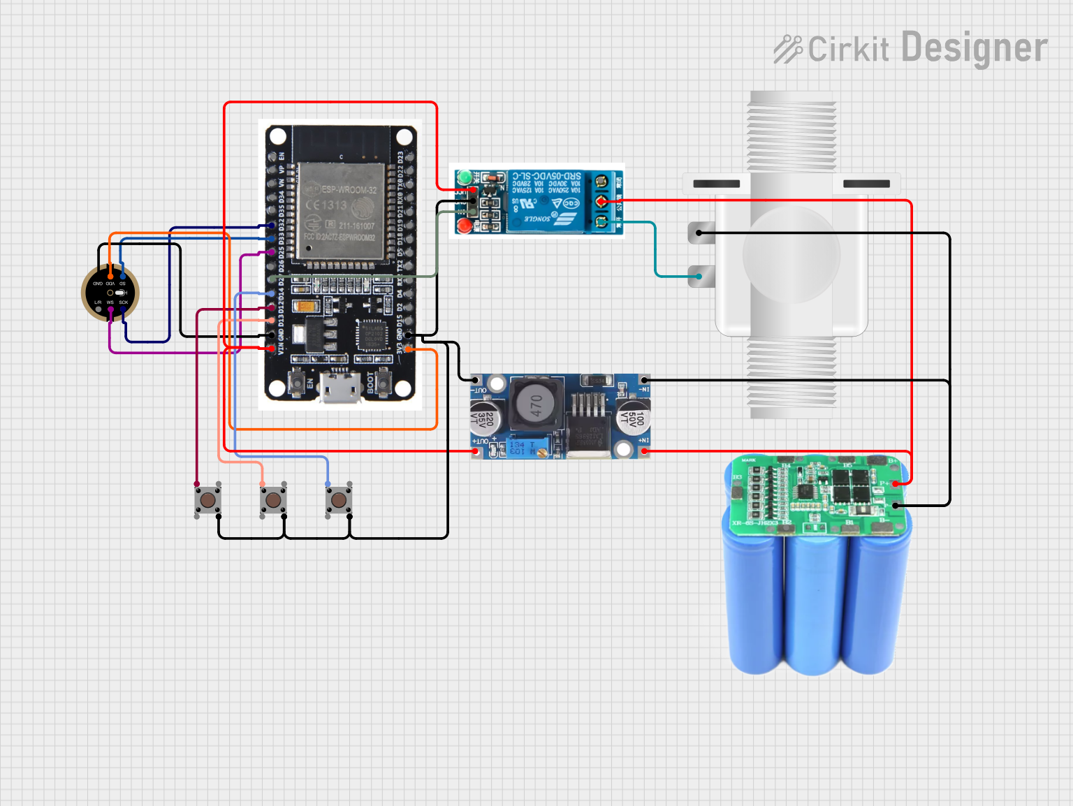
Example: Connecting INMP441 to Arduino UNO
The Arduino UNO does not have a native I2S interface, so you will need an external I2S interface module or use a microcontroller with built-in I2S support (e.g., ESP32). Below is an example of using the INMP441 with an ESP32:
Wiring Diagram
| INMP441 Pin | ESP32 Pin |
|---|---|
| VDD | 3.3V |
| GND | GND |
| WS | GPIO25 |
| SCK | GPIO26 |
| SD | GPIO22 |
| L/R | GND (Left) |
Example Code
#include <driver/i2s.h>

// I2S configuration
#define I2S_NUM         I2S_NUM_0  // I2S port number
#define I2S_WS          25         // Word Select pin
#define I2S_SCK         26         // Serial Clock pin
#define I2S_SD          22         // Serial Data pin

void setup() {
  // Configure I2S
  i2s_config_t i2s_config = {
    .mode = (i2s_mode_t)(I2S_MODE_MASTER | I2S_MODE_RX), // Master mode, receive data
    .sample_rate = 16000,                               // Sampling rate (16 kHz)
    .bits_per_sample = I2S_BITS_PER_SAMPLE_16BIT,       // 16-bit audio data
    .channel_format = I2S_CHANNEL_FMT_ONLY_LEFT,        // Use only the left channel
    .communication_format = I2S_COMM_FORMAT_I2S,        // I2S communication format
    .intr_alloc_flags = ESP_INTR_FLAG_LEVEL1,           // Interrupt level
    .dma_buf_count = 8,                                 // Number of DMA buffers
    .dma_buf_len = 64                                   // Length of each DMA buffer
  };

  // Configure I2S pins
  i2s_pin_config_t pin_config = {
    .bck_io_num = I2S_SCK,  // Serial Clock pin
    .ws_io_num = I2S_WS,    // Word Select pin
    .data_out_num = -1,     // Not used (output pin)
    .data_in_num = I2S_SD   // Serial Data pin
  };

  // Install and start I2S driver
  i2s_driver_install(I2S_NUM, &i2s_config, 0, NULL);
  i2s_set_pin(I2S_NUM, &pin_config);
}

void loop() {
  // Buffer to store audio data
  uint8_t audio_data[1024];
  size_t bytes_read;

  // Read audio data from INMP441
  i2s_read(I2S_NUM, audio_data, sizeof(audio_data), &bytes_read, portMAX_DELAY);

  // Process audio data (e.g., send to a server or save to storage)
}
Troubleshooting and FAQs
Common Issues and Solutions
No Audio Output:
- Verify the I2S clock signals (WS and SCK) are correctly configured.
- Ensure the L/R pin is properly connected to select the desired channel.
Distorted Audio:
- Check the power supply voltage and ensure it is within the specified range (1.8V to 3.3V).
- Avoid placing the microphone near sources of electromagnetic interference.
Low Sensitivity:
- Ensure the microphone is oriented correctly, with the sound port facing the audio source.
- Verify that the I2S configuration matches the microphone's output format.
FAQs
Q: Can the INMP441 be used with a 5V microcontroller?
A: The INMP441 operates at 1.8V to 3.3V. If using a 5V microcontroller, level shifters are required for the I2S signals.
Q: Does the INMP441 support stereo audio?
A: Yes, multiple INMP441 microphones can be used to capture stereo audio by configuring the L/R pin on each microphone.
Q: What is the maximum sampling rate supported?
A: The INMP441 supports sampling rates up to 48 kHz, depending on the I2S configuration.