How to Use EMERGENCY BUTTON: Examples, Pinouts, and Specs
Introduction
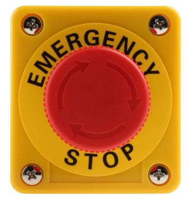
The Emergency Button is a safety device designed to trigger an immediate response when pressed. It is commonly used in industrial, commercial, and public settings to alert personnel, activate emergency protocols, or shut down machinery in hazardous situations. Its robust design ensures reliability in critical scenarios, making it an essential component in safety systems.
Explore Projects Built with EMERGENCY BUTTON
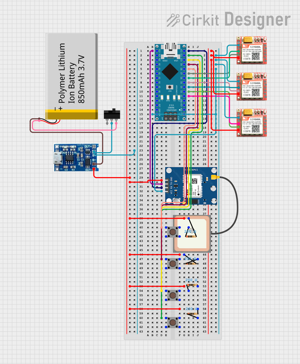

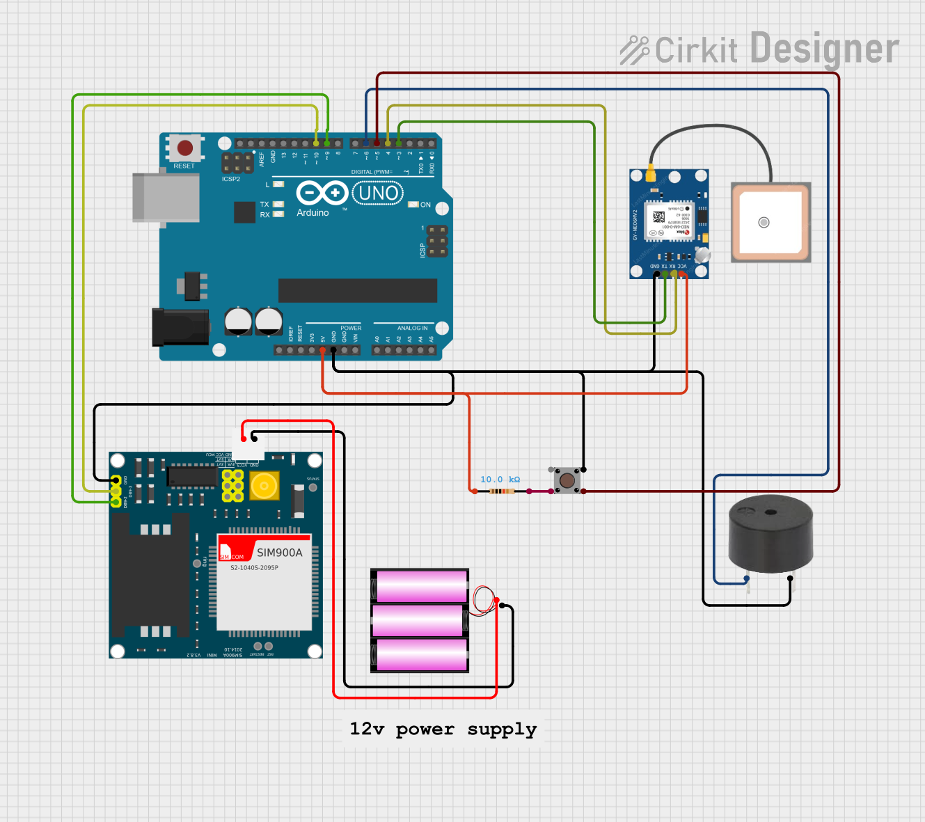
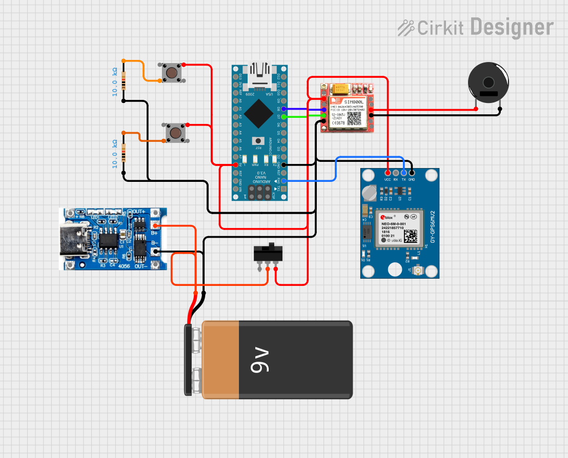
Explore Projects Built with EMERGENCY BUTTON
Common Applications and Use Cases
- Industrial machinery emergency stop systems
- Fire alarm activation points
- Elevator emergency controls
- Public transportation safety systems
- Security alarm triggers
Technical Specifications
Key Technical Details
| Parameter | Value |
|---|---|
| Operating Voltage | 12V to 24V DC |
| Contact Configuration | Normally Open (NO) or Normally Closed (NC) |
| Maximum Current Rating | 10A |
| Button Type | Push-to-activate, twist-to-reset |
| Material | High-durability plastic and metal |
| Mounting Style | Panel-mounted |
| Operating Temperature | -20°C to 70°C |
| IP Rating | IP65 (dust-tight and water-resistant) |
Pin Configuration and Descriptions
| Pin Name | Description |
|---|---|
| NO | Normally Open contact; closes when the button is pressed |
| NC | Normally Closed contact; opens when the button is pressed |
| COM | Common terminal; connects to either NO or NC based on the circuit design |
Usage Instructions
How to Use the Emergency Button in a Circuit
- Determine the Contact Configuration: Decide whether to use the Normally Open (NO) or Normally Closed (NC) contact based on your application. For example:
- Use NO for triggering an action when the button is pressed.
- Use NC for stopping an action when the button is pressed.
- Connect the Terminals:
- Connect the power source to the
COMterminal. - Connect the load or control circuit to either the
NOorNCterminal, depending on your configuration.
- Connect the power source to the
- Mount the Button: Securely mount the button on a panel or enclosure using the provided mounting hardware.
- Test the Circuit: Verify the functionality of the button by pressing it and observing the response in your circuit.
Important Considerations and Best Practices
- Ensure the button is rated for the voltage and current of your application.
- Use proper insulation and wiring to prevent short circuits or accidental activation.
- Regularly inspect the button for wear and tear, especially in high-use environments.
- For outdoor or harsh environments, ensure the button's IP rating meets the required standards.
Example: Connecting to an Arduino UNO
The Emergency Button can be used with an Arduino UNO to trigger an alert or stop a process. Below is an example circuit and code:
Circuit Setup
- Connect the
COMterminal of the button to the Arduino'sGND. - Connect the
NOterminal to a digital input pin (e.g.,D2) on the Arduino. - Use a pull-up resistor (10kΩ) between the digital input pin and
5Vto ensure a stable signal.
Arduino Code
// Emergency Button Example Code
// This code monitors the button state and triggers an alert when pressed.

const int buttonPin = 2;  // Pin connected to the NO terminal of the button
const int ledPin = 13;    // Built-in LED for visual alert

void setup() {
  pinMode(buttonPin, INPUT_PULLUP); // Set button pin as input with pull-up resistor
  pinMode(ledPin, OUTPUT);         // Set LED pin as output
  Serial.begin(9600);              // Initialize serial communication
}

void loop() {
  int buttonState = digitalRead(buttonPin); // Read the button state

  if (buttonState == LOW) { // Button pressed (NO contact closed)
    digitalWrite(ledPin, HIGH); // Turn on the LED
    Serial.println("Emergency Button Pressed!"); // Print alert message
  } else {
    digitalWrite(ledPin, LOW); // Turn off the LED
  }

  delay(100); // Small delay to debounce the button
}
Troubleshooting and FAQs
Common Issues and Solutions
Button Does Not Trigger the Circuit:
- Check the wiring connections to ensure the
COMandNO/NCterminals are correctly connected. - Verify that the button is not damaged or stuck.
- Check the wiring connections to ensure the
False Triggers or Unstable Behavior:
- Use a pull-up or pull-down resistor to stabilize the signal.
- Inspect the wiring for loose connections or interference.
Button Fails in Harsh Environments:
- Ensure the button's IP rating is suitable for the environment.
- Consider using a protective enclosure for additional durability.
FAQs
Q: Can the Emergency Button be used with AC circuits?
A: Yes, as long as the voltage and current ratings of the button are not exceeded. Ensure proper insulation and safety precautions when working with AC circuits.
Q: How do I reset the button after pressing it?
A: Most emergency buttons are designed with a twist-to-reset mechanism. Rotate the button clockwise to reset it.
Q: Can I use the button for low-power applications?
A: Yes, the button can be used for low-power applications, such as triggering a microcontroller input, as long as the voltage and current are within the specified range.
Q: What is the lifespan of the Emergency Button?
A: The lifespan depends on the manufacturer and usage conditions but typically ranges from 50,000 to 100,000 cycles. Regular maintenance can extend its life.