
How to Use moto driver 6600: Examples, Pinouts, and Specs
 Design with moto driver 6600 in Cirkit Designer
Introduction
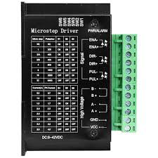
The Moto Driver 6600 is a versatile motor driver IC designed to control both DC motors and stepper motors. It provides high current output and enables precise control of motor speed and direction, making it an essential component for robotics, automation, and motorized systems. Its robust design ensures reliable performance in a wide range of applications.
Explore Projects Built with moto driver 6600
 Open Project in Cirkit Designer
 Open Project in Cirkit Designer
 Open Project in Cirkit Designer
 Open Project in Cirkit Designer
Explore Projects Built with moto driver 6600
Open Project in Cirkit DesignerOpen Project in Cirkit DesignerOpen Project in Cirkit DesignerOpen Project in Cirkit DesignerCommon Applications
- Robotics and automation systems
- Electric vehicles and motorized toys
- CNC machines and 3D printers
- Conveyor belts and industrial machinery
- DIY projects involving motor control
Technical Specifications
The Moto Driver 6600 is engineered to handle demanding motor control tasks. Below are its key technical specifications:
| Parameter | Value |
|---|---|
| Operating Voltage | 4.5V to 36V |
| Output Current (per channel) | Up to 3A continuous, 4A peak |
| Control Logic Voltage | 3.3V or 5V compatible |
| Motor Types Supported | DC motors, Stepper motors |
| PWM Frequency | Up to 100 kHz |
| Thermal Shutdown | Yes |
| Overcurrent Protection | Yes |
| Operating Temperature | -40°C to +85°C |
Pin Configuration and Descriptions
The Moto Driver 6600 typically comes in a 16-pin package. Below is the pinout and description:
| Pin Number | Pin Name | Description |
|---|---|---|
| 1 | IN1 | Input signal for controlling motor direction (Channel 1) |
| 2 | IN2 | Input signal for controlling motor direction (Channel 2) |
| 3 | ENA | Enable pin for Channel 1 (PWM input for speed control) |
| 4 | ENB | Enable pin for Channel 2 (PWM input for speed control) |
| 5 | OUT1 | Output pin for motor connection (Channel 1) |
| 6 | OUT2 | Output pin for motor connection (Channel 1) |
| 7 | OUT3 | Output pin for motor connection (Channel 2) |
| 8 | OUT4 | Output pin for motor connection (Channel 2) |
| 9 | VCC | Power supply for motors (4.5V to 36V) |
| 10 | GND | Ground connection |
| 11 | CS1 | Current sense pin for Channel 1 (optional, for monitoring current) |
| 12 | CS2 | Current sense pin for Channel 2 (optional, for monitoring current) |
| 13 | NC | Not connected |
| 14 | NC | Not connected |
| 15 | VM | Logic voltage input (3.3V or 5V) |
| 16 | STBY | Standby mode pin (active low, pull high to enable the driver) |
Usage Instructions
Using the Moto Driver 6600 in a Circuit
- Power Supply: Connect the motor power supply to the
VCCpin and ground to theGNDpin. Ensure the voltage is within the operating range (4.5V to 36V). - Logic Voltage: Provide a 3.3V or 5V logic voltage to the
VMpin. - Motor Connections: Connect the motor terminals to the
OUT1,OUT2,OUT3, andOUT4pins as required.- For a single DC motor, use
OUT1andOUT2(Channel 1) orOUT3andOUT4(Channel 2). - For a stepper motor, connect the motor coils to all four output pins.
- For a single DC motor, use
- Control Signals: Use the
IN1,IN2,ENA, andENBpins to control motor speed and direction.- Apply PWM signals to
ENAandENBfor speed control. - Set
IN1andIN2high/low to control the direction of rotation.
- Apply PWM signals to
- Standby Mode: Pull the
STBYpin high to enable the driver. Pull it low to put the driver in standby mode.
Arduino UNO Example Code
Below is an example of how to control a DC motor using the Moto Driver 6600 and an Arduino UNO:
// Define motor control pins
const int IN1 = 7;  // Direction control pin for Channel 1
const int IN2 = 8;  // Direction control pin for Channel 1
const int ENA = 9;  // PWM speed control pin for Channel 1

void setup() {
  // Set motor control pins as outputs
  pinMode(IN1, OUTPUT);
  pinMode(IN2, OUTPUT);
  pinMode(ENA, OUTPUT);
}

void loop() {
  // Rotate motor in one direction
  digitalWrite(IN1, HIGH);  // Set IN1 high
  digitalWrite(IN2, LOW);   // Set IN2 low
  analogWrite(ENA, 128);    // Set speed to 50% (PWM value: 128 out of 255)
  delay(2000);              // Run for 2 seconds

  // Stop the motor
  analogWrite(ENA, 0);      // Set speed to 0
  delay(1000);              // Wait for 1 second

  // Rotate motor in the opposite direction
  digitalWrite(IN1, LOW);   // Set IN1 low
  digitalWrite(IN2, HIGH);  // Set IN2 high
  analogWrite(ENA, 200);    // Set speed to ~78% (PWM value: 200 out of 255)
  delay(2000);              // Run for 2 seconds

  // Stop the motor
  analogWrite(ENA, 0);      // Set speed to 0
  delay(1000);              // Wait for 1 second
}
Important Considerations
- Heat Dissipation: The Moto Driver 6600 can generate heat during operation. Use a heat sink or ensure proper ventilation to prevent overheating.
- Current Limits: Do not exceed the maximum current rating (3A continuous, 4A peak) to avoid damaging the IC.
- Decoupling Capacitors: Place a decoupling capacitor (e.g., 100 µF) near the
VCCpin to stabilize the power supply.
Troubleshooting and FAQs
Common Issues and Solutions
Motor Not Spinning
- Cause: Incorrect wiring or insufficient power supply.
- Solution: Double-check all connections and ensure the power supply voltage is within the specified range.
Overheating
- Cause: Excessive current draw or inadequate heat dissipation.
- Solution: Use a heat sink or fan, and ensure the motor's current requirements are within the IC's limits.
Erratic Motor Behavior
- Cause: Noise or unstable power supply.
- Solution: Add decoupling capacitors near the power pins and ensure a stable power source.
No Response from the Driver
- Cause:
STBYpin is not pulled high. - Solution: Ensure the
STBYpin is connected to a high logic level (3.3V or 5V).
- Cause:
FAQs
Can I use the Moto Driver 6600 with a 12V motor? Yes, the Moto Driver 6600 supports motor voltages from 4.5V to 36V, so a 12V motor is compatible.
What is the maximum PWM frequency supported? The Moto Driver 6600 supports PWM frequencies up to 100 kHz.
Can I control two DC motors simultaneously? Yes, the Moto Driver 6600 has two channels, allowing you to control two DC motors independently.
Is the Moto Driver 6600 compatible with Raspberry Pi? Yes, the Moto Driver 6600 is compatible with 3.3V logic, making it suitable for use with Raspberry Pi.
This concludes the documentation for the Moto Driver 6600.