How to Use OLED 128x64 I2C Monochrome Display VDD-GND: Examples, Pinouts, and Specs
Introduction
The OLED 128x64 I2C Monochrome Display is a compact and versatile display module that offers high contrast and sharp images with its 128x64 pixel resolution. Utilizing Organic Light Emitting Diode (OLED) technology, this display can produce deep blacks and high brightness levels, making it suitable for a wide range of applications. Its I2C interface simplifies connectivity, requiring fewer pins and easing the communication process with microcontrollers like the Arduino UNO.
Explore Projects Built with OLED 128x64 I2C Monochrome Display VDD-GND
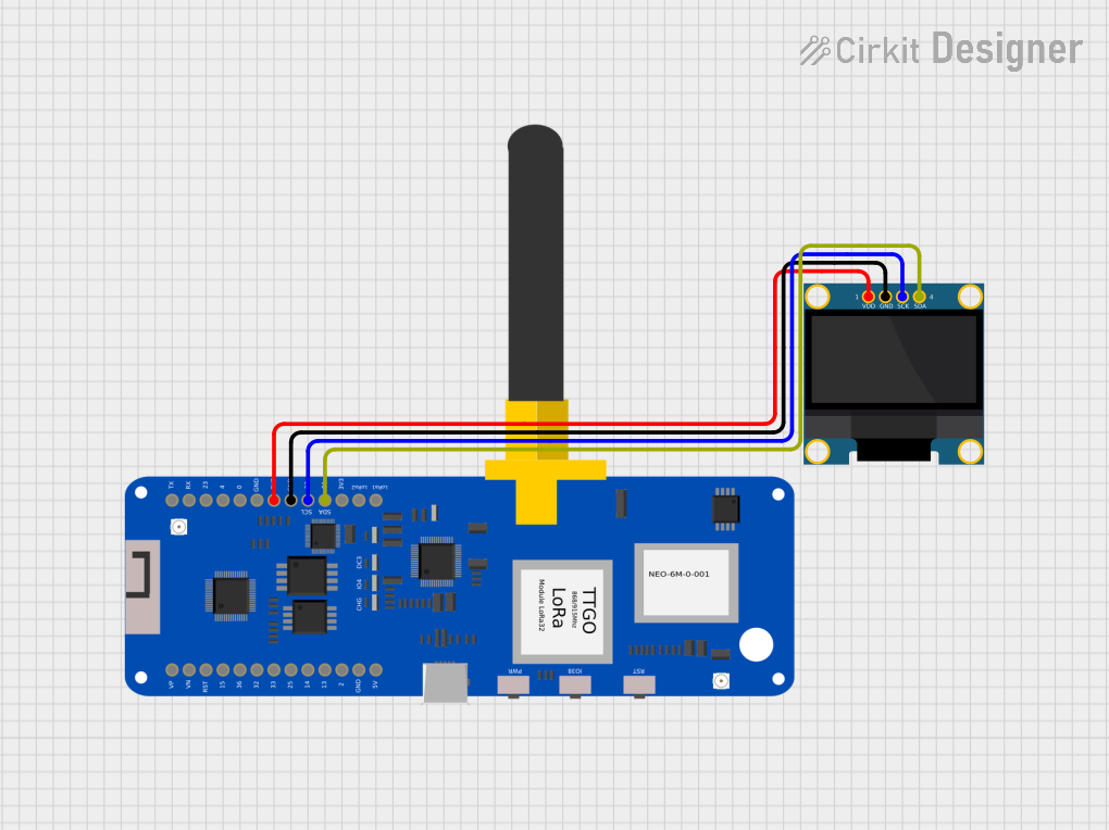

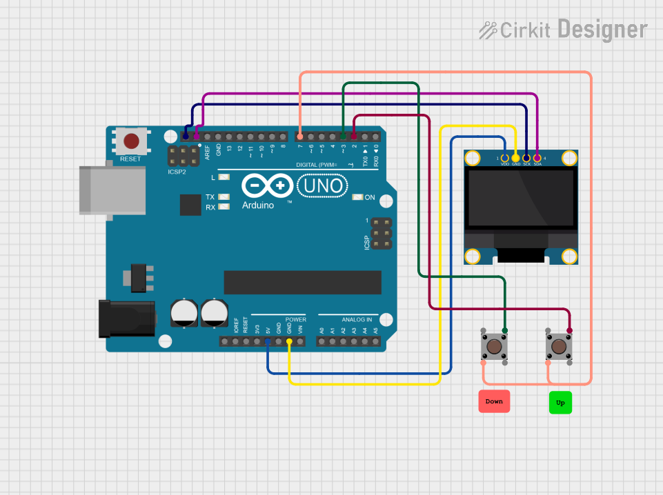

Explore Projects Built with OLED 128x64 I2C Monochrome Display VDD-GND
Common Applications and Use Cases
- User interfaces for embedded systems
- Real-time data display for sensors
- Portable electronic devices
- Wearable technology
- DIY projects and hobbyist electronics
Technical Specifications
Key Technical Details
- Display Type: Monochrome OLED
- Resolution: 128x64 pixels
- Communication: I2C (Inter-Integrated Circuit)
- Operating Voltage: 3.3V to 5V
- Current Consumption: 10mA (typical), 150mA (max)
- Viewing Angle: >160 degrees
- Operating Temperature: -30°C to 70°C
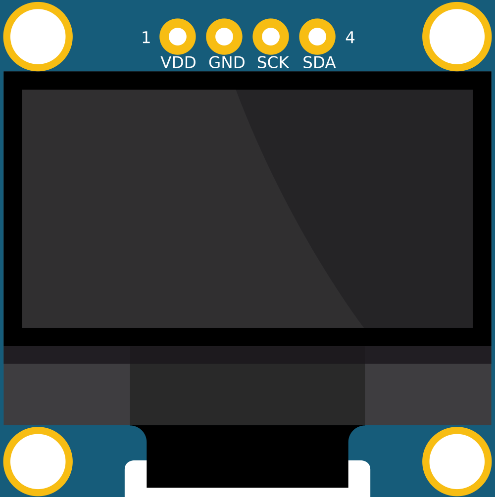
Pin Configuration and Descriptions
| Pin Number | Pin Name | Description |
|---|---|---|
| 1 | GND | Ground |
| 2 | VDD | Power supply (3.3V to 5V) |
| 3 | SCK | I2C Clock Line |
| 4 | SDA | I2C Data Line |
Usage Instructions
Integrating the Display into a Circuit
- Connect the GND pin to the ground of the power supply.
- Connect the VDD pin to a 3.3V or 5V power supply.
- Connect the SCK pin to the I2C clock pin (SCL) of the microcontroller.
- Connect the SDA pin to the I2C data pin (SDA) of the microcontroller.
Important Considerations and Best Practices
- Ensure that the power supply voltage matches the operating voltage of the display.
- Use pull-up resistors on the I2C lines if they are not already present on the microcontroller board.
- Avoid exposing the display to direct sunlight or high temperatures to prevent damage.
- When handling the display, take precautions against electrostatic discharge (ESD).
Example Code for Arduino UNO
#include <Wire.h>
#include <Adafruit_GFX.h>
#include <Adafruit_SSD1306.h>

// OLED display TWI address
#define OLED_ADDR   0x3C

// Reset pin not used on 4-pin OLED module
Adafruit_SSD1306 display(128, 64, &Wire, -1);

void setup() {
  // Initialize with the I2C addr 0x3C (for the 128x64)
  if(!display.begin(SSD1306_SWITCHCAPVCC, OLED_ADDR)) {
    Serial.println(F("SSD1306 allocation failed"));
    for(;;); // Don't proceed, loop forever
  }

  // Clear the buffer
  display.clearDisplay();

  // Draw a single pixel in white
  display.drawPixel(10, 10, WHITE);

  // Display the drawing
  display.display();
}

void loop() {
  // Nothing here for now
}
Troubleshooting and FAQs
Common Issues
- Display not powering on: Check the VDD and GND connections for proper voltage and secure connections.
- No data on display: Ensure that the I2C lines are connected correctly and that the correct I2C address is used in the code.
- Dim or flickering display: Verify that the power supply can deliver sufficient current and is not dropping below the operating voltage.
Solutions and Tips for Troubleshooting
- Double-check all connections and solder joints for continuity and shorts.
- Use a multimeter to verify the voltage levels at the VDD pin.
- If using long wires for I2C communication, consider using shielded cables to prevent noise.
- Consult the datasheet of the SSD1306 controller (commonly used in these displays) for advanced troubleshooting.
FAQs
Q: Can I use this display with a 5V Arduino? A: Yes, the display can be powered with 5V, and it is compatible with 5V logic levels.
Q: How do I change the I2C address? A: The I2C address is typically fixed for these modules. If you need to use multiple displays, look for versions with configurable addresses or use an I2C multiplexer.
Q: Can the display show graphics and text? A: Yes, the display can show both graphics and text. The Adafruit GFX library provides functions for drawing shapes and text.
Q: Is it possible to use this display with other microcontrollers? A: Absolutely, as long as the microcontroller supports I2C communication and you have the appropriate library for the display controller.