How to Use ACCL Automatic Changeover Switch : Examples, Pinouts, and Specs
Introduction
The ACCL (Automatic Changeover Switch) is an essential device designed to ensure uninterrupted power supply by automatically switching between two power sources. Typically used in residential, commercial, and industrial applications, the ACCL monitors the availability of the primary power source and seamlessly switches to a backup source, such as a generator or an inverter, during outages or failures. This functionality eliminates the need for manual intervention, providing convenience and reliability.
Explore Projects Built with ACCL Automatic Changeover Switch


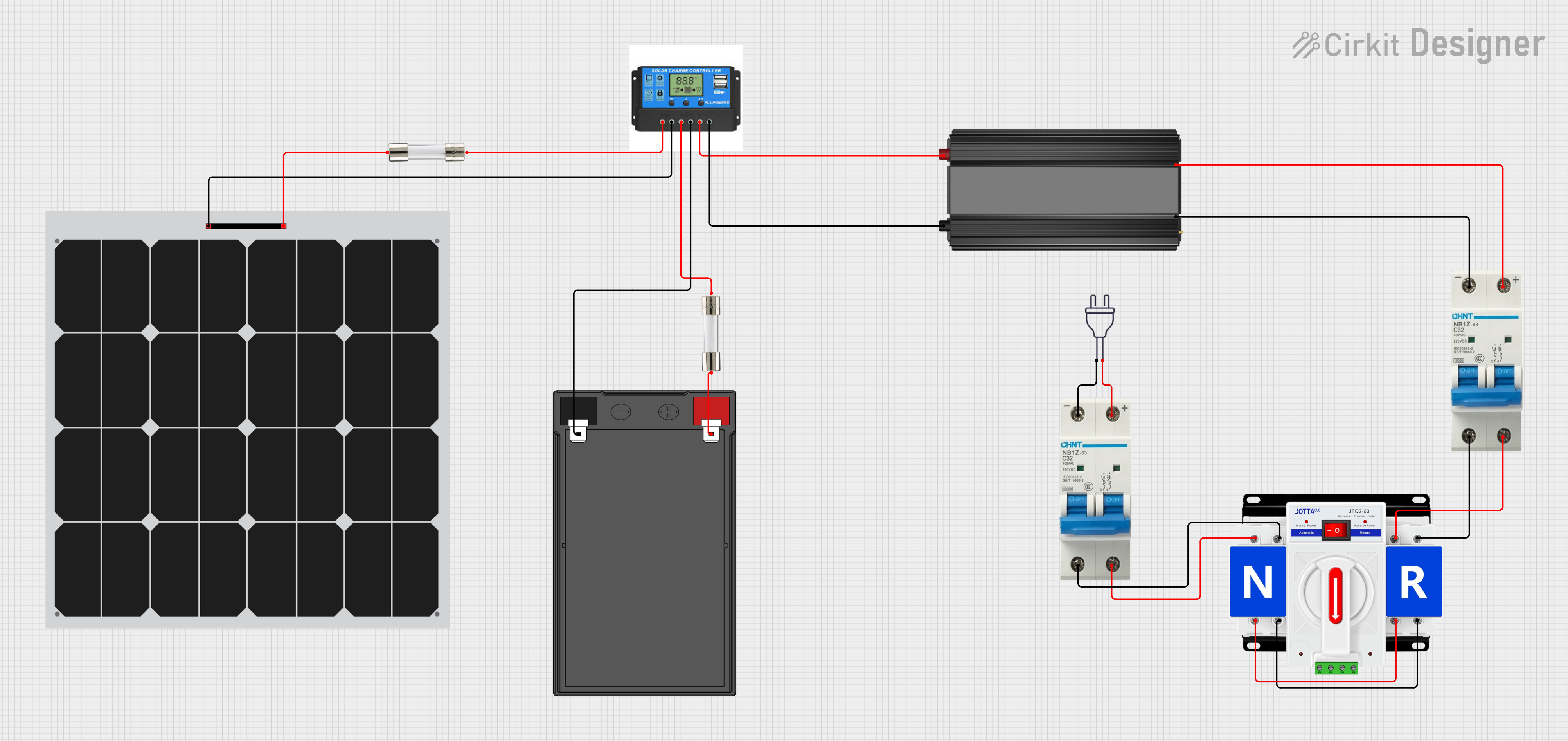
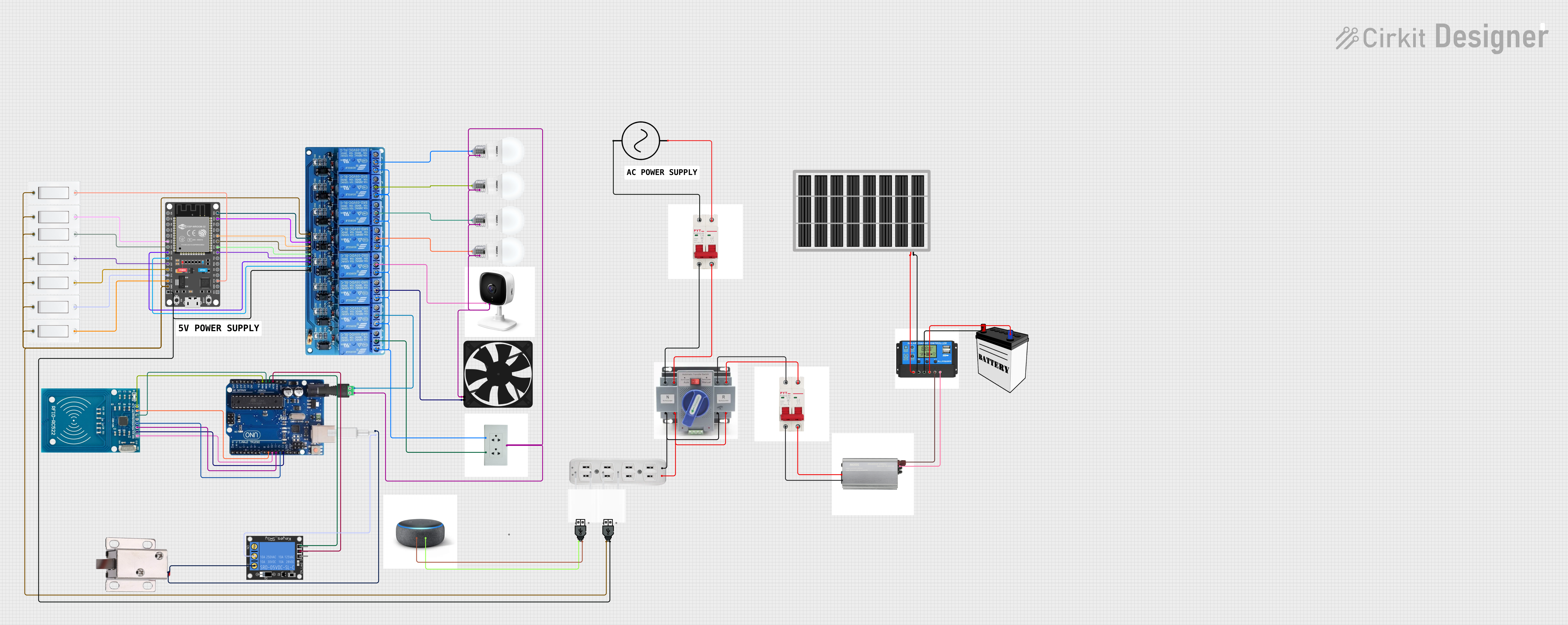
Explore Projects Built with ACCL Automatic Changeover Switch
Common Applications and Use Cases
- Residential buildings for switching between grid power and backup generators.
- Commercial establishments to maintain operations during power outages.
- Industrial facilities requiring continuous power for critical equipment.
- Data centers to ensure uninterrupted power supply to servers and networking equipment.
Technical Specifications
Key Technical Details
- Operating Voltage: 110V AC to 440V AC (varies by model)
- Frequency: 50Hz/60Hz
- Current Rating: 16A, 32A, 63A, or higher (depending on the model)
- Switching Time: Typically 2-5 seconds
- Power Source Compatibility: Grid power, generators, inverters
- Control Type: Automatic
- Operating Temperature: -10°C to 55°C
- Enclosure: IP-rated for protection against dust and moisture (e.g., IP54)
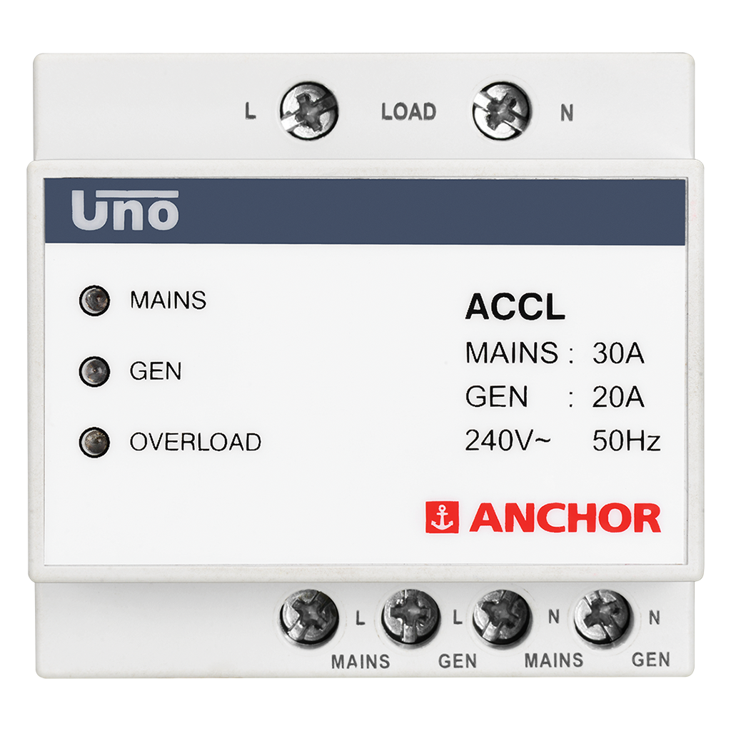
Pin Configuration and Descriptions
The ACCL typically has terminals for connecting the primary power source, backup power source, and load. Below is a general pin configuration:
| Pin/Terminal | Description |
|---|---|
| L1 (Primary Line) | Input terminal for the primary power source (e.g., grid power). |
| N1 (Primary Neutral) | Neutral terminal for the primary power source. |
| L2 (Backup Line) | Input terminal for the backup power source (e.g., generator or inverter). |
| N2 (Backup Neutral) | Neutral terminal for the backup power source. |
| L (Load Line) | Output terminal for the load (connected to appliances or equipment). |
| N (Load Neutral) | Neutral terminal for the load. |
| Ground (GND) | Grounding terminal for safety and protection against electrical faults. |
Note: The exact pin configuration may vary depending on the manufacturer and model. Always refer to the specific datasheet for your ACCL.
Usage Instructions
How to Use the ACCL in a Circuit
Wiring the ACCL:
- Connect the primary power source (e.g., grid power) to the L1 and N1 terminals.
- Connect the backup power source (e.g., generator or inverter) to the L2 and N2 terminals.
- Connect the load (appliances or equipment) to the L and N terminals.
- Ensure proper grounding by connecting the GND terminal to an appropriate earth point.
Power Source Configuration:
- Set the ACCL to prioritize the primary power source. When the primary source is available, it will supply power to the load.
- In the event of a primary source failure, the ACCL will automatically switch to the backup source.
Testing the Setup:
- Simulate a power outage by disconnecting the primary source. Verify that the ACCL switches to the backup source within the specified switching time.
- Restore the primary source and confirm that the ACCL switches back automatically.
Important Considerations and Best Practices
- Load Capacity: Ensure the ACCL's current rating matches or exceeds the total load current.
- Backup Source Compatibility: Verify that the backup source (e.g., generator) is compatible with the ACCL's voltage and frequency requirements.
- Wiring Safety: Use appropriate wire gauges and follow local electrical codes during installation.
- Maintenance: Periodically inspect the ACCL for signs of wear, loose connections, or damage.
- Delay Settings: Some ACCLs allow configuring a delay before switching to the backup source. Adjust this setting as needed to prevent unnecessary switching.
Arduino Integration (Optional Monitoring)
While the ACCL operates independently, you can use an Arduino UNO to monitor its status (e.g., which power source is active). Below is an example code snippet:
// Example: Monitoring ACCL status using Arduino UNO
// Connect digital pins to ACCL status output (if available).

const int primaryStatusPin = 2; // Pin connected to primary source status
const int backupStatusPin = 3;  // Pin connected to backup source status

void setup() {
  pinMode(primaryStatusPin, INPUT); // Set primary status pin as input
  pinMode(backupStatusPin, INPUT);  // Set backup status pin as input
  Serial.begin(9600);              // Initialize serial communication
}

void loop() {
  int primaryStatus = digitalRead(primaryStatusPin); // Read primary status
  int backupStatus = digitalRead(backupStatusPin);   // Read backup status

  if (primaryStatus == HIGH) {
    Serial.println("Primary power source is active.");
  } else if (backupStatus == HIGH) {
    Serial.println("Backup power source is active.");
  } else {
    Serial.println("No power source is active.");
  }

  delay(1000); // Wait for 1 second before next reading
}
Note: Ensure the ACCL has status output pins compatible with Arduino logic levels (5V or 3.3V).
Troubleshooting and FAQs
Common Issues and Solutions
ACCL Does Not Switch to Backup Source:
- Cause: Backup source is not properly connected or configured.
- Solution: Verify the wiring and ensure the backup source is operational and within the ACCL's voltage and frequency range.
Frequent Switching Between Sources:
- Cause: Unstable primary power source or incorrect delay settings.
- Solution: Check the primary source for stability and adjust the delay settings to prevent rapid switching.
No Power to Load:
- Cause: Loose connections or blown fuses.
- Solution: Inspect all connections and replace any damaged fuses.
ACCL Overheating:
- Cause: Overloading or poor ventilation.
- Solution: Ensure the load does not exceed the ACCL's current rating and provide adequate ventilation.
FAQs
Q: Can the ACCL be used with solar inverters?
A: Yes, as long as the inverter's output voltage and frequency are compatible with the ACCL.Q: What happens if both power sources fail?
A: The ACCL will not supply power to the load until at least one source becomes available.Q: Is manual intervention required to reset the ACCL after switching?
A: No, the ACCL automatically resets and switches back to the primary source when it becomes available.Q: Can the ACCL handle three-phase power?
A: Some ACCL models are designed for three-phase systems. Check the specifications of your model.
By following this documentation, users can effectively install, operate, and troubleshoot the ACCL Automatic Changeover Switch for reliable power management.