How to Use Pixhawk 2.4.8: Examples, Pinouts, and Specs
Introduction
The Pixhawk 2.4.8 is a versatile open-source flight control hardware designed for drones and other unmanned vehicles. It features advanced sensors, GPS integration, and compatibility with various autopilot software such as ArduPilot and PX4. This flight controller is widely used in applications ranging from hobbyist drones to professional-grade unmanned aerial vehicles (UAVs). Its robust design and extensive feature set make it a popular choice for developers and enthusiasts alike.
Explore Projects Built with Pixhawk 2.4.8


Explore Projects Built with Pixhawk 2.4.8
Common Applications and Use Cases
- Multirotor drones (quadcopters, hexacopters, etc.)
- Fixed-wing UAVs
- Autonomous ground vehicles
- Marine vehicles (e.g., autonomous boats)
- Research and development in robotics and automation
- Aerial photography and videography
- Surveying and mapping
Technical Specifications
The Pixhawk 2.4.8 is equipped with powerful hardware and a wide range of interfaces to support various sensors and peripherals. Below are its key technical details:
Key Technical Details
- Processor: 32-bit STM32F427 Cortex-M4, 168 MHz, with hardware floating-point unit
- RAM: 256 KB
- Flash Memory: 2 MB
- IMU Sensors:
- MPU6000 (3-axis accelerometer and gyroscope)
- LSM303D (3-axis magnetometer)
- MS5611 (barometer)
- Input Voltage: 4.8V to 5.4V (via power module)
- Power Consumption: ~100 mA @ 5V (excluding peripherals)
- Interfaces:
- 14 PWM/servo outputs
- 5 UART ports
- I2C, SPI, CAN, and ADC ports
- Micro-USB for configuration and firmware updates
- GPS Support: External GPS module with compass (e.g., Ublox NEO-M8N)
- Dimensions: 81.5 mm x 50 mm x 15.5 mm
- Weight: ~38 grams
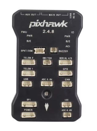
Pin Configuration and Descriptions
The Pixhawk 2.4.8 features multiple connectors for peripherals. Below is a summary of the key pin configurations:
Power Input and Output
| Pin Name | Description |
|---|---|
| Power Module | Main power input (4.8V to 5.4V) |
| Servo Rail | Supplies power to connected servos |
| USB Port | For powering and configuring the device |
Peripheral Connections
| Port Name | Description |
|---|---|
| GPS | Connects to external GPS module |
| I2C | For connecting I2C-based sensors |
| CAN | For CAN bus communication |
| UART | Serial communication with peripherals |
| ADC | Analog-to-digital converter inputs |
PWM/Servo Outputs
| Pin Range | Description |
|---|---|
| PWM 1-8 | Primary motor/servo outputs |
| PWM 9-14 | Auxiliary motor/servo outputs |
Usage Instructions
How to Use the Pixhawk 2.4.8 in a Circuit
Powering the Pixhawk:
- Use the included power module to supply a stable voltage (4.8V to 5.4V).
- Alternatively, power the device via the USB port for configuration purposes.
Connecting Peripherals:
- Attach the GPS module to the GPS port.
- Connect additional sensors (e.g., rangefinders, cameras) to the appropriate I2C, UART, or ADC ports.
- Use the PWM outputs to connect motors or servos.
Firmware Installation:
- Download the latest firmware (e.g., ArduPilot or PX4) from the official website.
- Connect the Pixhawk to your computer via USB and use a ground control software (e.g., Mission Planner or QGroundControl) to upload the firmware.
Calibrating Sensors:
- Use the ground control software to calibrate the accelerometer, gyroscope, compass, and radio transmitter.
Flight Testing:
- Perform a pre-flight check to ensure all sensors and motors are functioning correctly.
- Test the system in a controlled environment before deploying it in real-world applications.
Important Considerations and Best Practices
- Always use a stable power source to avoid voltage fluctuations that may cause the Pixhawk to reboot mid-flight.
- Ensure proper vibration damping to prevent inaccurate sensor readings.
- Regularly update the firmware to benefit from the latest features and bug fixes.
- Use a compatible GPS module with an integrated compass for accurate navigation.
- Perform a failsafe configuration to handle signal loss or low battery scenarios.
Example: Connecting Pixhawk 2.4.8 to Arduino UNO
The Pixhawk can communicate with an Arduino UNO via UART. Below is an example code snippet for reading data from the Pixhawk:
#include <SoftwareSerial.h>

// Define RX and TX pins for communication with Pixhawk
SoftwareSerial pixhawkSerial(10, 11); // RX = pin 10, TX = pin 11

void setup() {
  // Initialize serial communication
  Serial.begin(9600); // For debugging via Serial Monitor
  pixhawkSerial.begin(57600); // Pixhawk default baud rate

  Serial.println("Pixhawk-Arduino Communication Initialized");
}

void loop() {
  // Check if data is available from Pixhawk
  if (pixhawkSerial.available()) {
    // Read and print data from Pixhawk
    char data = pixhawkSerial.read();
    Serial.print("Received: ");
    Serial.println(data);
  }
}
Note: Ensure the Pixhawk's UART port is configured to send data to the Arduino UNO.
Troubleshooting and FAQs
Common Issues and Solutions
Pixhawk Not Powering On:
- Check the power module connection and ensure the input voltage is within the specified range.
- Verify that the USB cable is functional if powering via USB.
GPS Not Detected:
- Ensure the GPS module is securely connected to the GPS port.
- Check the ground control software for GPS configuration settings.
Inaccurate Sensor Readings:
- Verify that the Pixhawk is mounted on a vibration-damped platform.
- Recalibrate the sensors using the ground control software.
Firmware Upload Fails:
- Ensure the USB cable is properly connected.
- Restart the Pixhawk and try uploading the firmware again.
FAQs
Q: Can the Pixhawk 2.4.8 be used with fixed-wing aircraft?
A: Yes, the Pixhawk 2.4.8 supports fixed-wing aircraft and can be configured using compatible autopilot software.
Q: What is the maximum number of motors the Pixhawk can control?
A: The Pixhawk 2.4.8 can control up to 14 motors/servos using its PWM outputs.
Q: Is the Pixhawk 2.4.8 waterproof?
A: No, the Pixhawk 2.4.8 is not waterproof. It should be protected from water and moisture during use.
Q: Can I use the Pixhawk without a GPS module?
A: Yes, but GPS is required for autonomous navigation and position hold modes.
Q: How do I reset the Pixhawk to factory settings?
A: Use the ground control software to perform a parameter reset or reflash the firmware.