Cirkit Designer Logo
Cirkit Designer
Your all-in-one circuit design IDE
Home / 
Component Documentation

How to Use CTVIB01 0-5V to 4-20mA Converter: Examples, Pinouts, and Specs

Image of CTVIB01 0-5V to 4-20mA Converter
Cirkit Designer LogoDesign with CTVIB01 0-5V to 4-20mA Converter in Cirkit Designer

Introduction

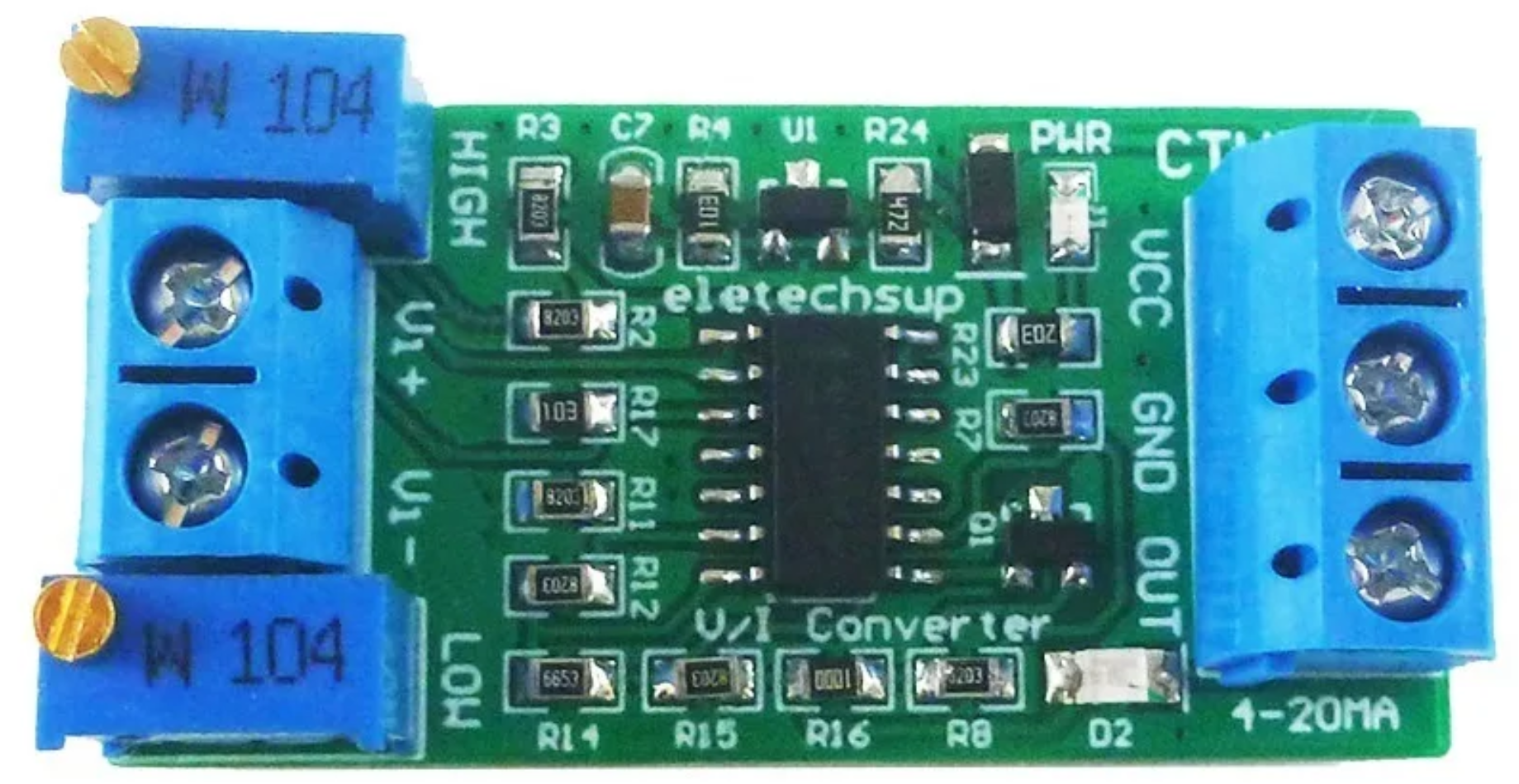
The CTVIB01 is a precision device manufactured by ELETECHSUP designed to convert a 0-5V voltage signal into a 4-20mA current signal. This conversion is essential in industrial and automation systems where current signals are preferred for transmitting data over long distances due to their resilience to noise and voltage drops.

Explore Projects Built with CTVIB01 0-5V to 4-20mA Converter

Use Cirkit Designer to design, explore, and prototype these projects online. Some projects support real-time simulation. Click "Open Project" to start designing instantly!
ESP32-Based Smart Energy Monitoring and Control System
Image of SMART SOCKET: A project utilizing CTVIB01 0-5V to 4-20mA Converter in a practical application
This circuit is designed to monitor AC voltage and current using ZMPT101B and ZMCT103C sensors, respectively, with an ESP32 microcontroller processing the sensor outputs. The XL4015 step-down module regulates the power supply to provide a stable voltage to the sensors, the ESP32, and an LCD I2C display. The ESP32 controls a 4-channel relay module for switching AC loads, and the system's operation can be interacted with via the LCD display and a push switch.
Cirkit Designer LogoOpen Project in Cirkit Designer
Arduino Mega 2560-Based Robotic System with Stepper Motors and IR Sensors
Image of FYP: A project utilizing CTVIB01 0-5V to 4-20mA Converter in a practical application
This circuit is a control system powered by a 12V to 5V step-down converter, featuring an Arduino Mega 2560 microcontroller that interfaces with various sensors (IR sensors, limit switch), actuators (servos, stepper motors), and a 20x4 LCD display. The system is designed to monitor inputs from sensors and control outputs to motors and display information, suitable for applications like automation or robotics.
Cirkit Designer LogoOpen Project in Cirkit Designer
ESP32-Controlled Smart Lighting System with Power Monitoring
Image of Energy Monitoring System: A project utilizing CTVIB01 0-5V to 4-20mA Converter in a practical application
This circuit appears to be a multi-channel current monitoring system using several ACS712 current sensors to measure the current through different loads, likely bulbs connected to a 220V power source. The current readings from the sensors are digitized by an Adafruit ADS1115 16-bit ADC, which interfaces with an ESP32 microcontroller via I2C communication for further processing or telemetry. A buck converter is used to step down the voltage to power the ESP32 and the sensors, and the system is powered through a 2.1mm DC barrel jack, indicating it is designed for external power supply.
Cirkit Designer LogoOpen Project in Cirkit Designer
ESP32-Based Industrial Control System with RS485 Communication and I2C Interface
Image of DRIVER TESTER : A project utilizing CTVIB01 0-5V to 4-20mA Converter in a practical application
This circuit integrates a microcontroller with a display, digital potentiometer, IO expander, and opto-isolator board for signal interfacing and isolation. It includes a UART to RS485 converter for serial communication and a power converter to step down voltage for the system. The circuit is designed for control and communication in an isolated and protected environment.
Cirkit Designer LogoOpen Project in Cirkit Designer

Explore Projects Built with CTVIB01 0-5V to 4-20mA Converter

Use Cirkit Designer to design, explore, and prototype these projects online. Some projects support real-time simulation. Click "Open Project" to start designing instantly!
Image of SMART SOCKET: A project utilizing CTVIB01 0-5V to 4-20mA Converter in a practical application
ESP32-Based Smart Energy Monitoring and Control System
This circuit is designed to monitor AC voltage and current using ZMPT101B and ZMCT103C sensors, respectively, with an ESP32 microcontroller processing the sensor outputs. The XL4015 step-down module regulates the power supply to provide a stable voltage to the sensors, the ESP32, and an LCD I2C display. The ESP32 controls a 4-channel relay module for switching AC loads, and the system's operation can be interacted with via the LCD display and a push switch.
Cirkit Designer LogoOpen Project in Cirkit Designer
Image of FYP: A project utilizing CTVIB01 0-5V to 4-20mA Converter in a practical application
Arduino Mega 2560-Based Robotic System with Stepper Motors and IR Sensors
This circuit is a control system powered by a 12V to 5V step-down converter, featuring an Arduino Mega 2560 microcontroller that interfaces with various sensors (IR sensors, limit switch), actuators (servos, stepper motors), and a 20x4 LCD display. The system is designed to monitor inputs from sensors and control outputs to motors and display information, suitable for applications like automation or robotics.
Cirkit Designer LogoOpen Project in Cirkit Designer
Image of Energy Monitoring System: A project utilizing CTVIB01 0-5V to 4-20mA Converter in a practical application
ESP32-Controlled Smart Lighting System with Power Monitoring
This circuit appears to be a multi-channel current monitoring system using several ACS712 current sensors to measure the current through different loads, likely bulbs connected to a 220V power source. The current readings from the sensors are digitized by an Adafruit ADS1115 16-bit ADC, which interfaces with an ESP32 microcontroller via I2C communication for further processing or telemetry. A buck converter is used to step down the voltage to power the ESP32 and the sensors, and the system is powered through a 2.1mm DC barrel jack, indicating it is designed for external power supply.
Cirkit Designer LogoOpen Project in Cirkit Designer
Image of DRIVER TESTER : A project utilizing CTVIB01 0-5V to 4-20mA Converter in a practical application
ESP32-Based Industrial Control System with RS485 Communication and I2C Interface
This circuit integrates a microcontroller with a display, digital potentiometer, IO expander, and opto-isolator board for signal interfacing and isolation. It includes a UART to RS485 converter for serial communication and a power converter to step down voltage for the system. The circuit is designed for control and communication in an isolated and protected environment.
Cirkit Designer LogoOpen Project in Cirkit Designer

Common Applications and Use Cases

  • Industrial Automation: Transmitting sensor data (e.g., temperature, pressure, or flow) to a central controller.
  • Process Control Systems: Interfacing with Programmable Logic Controllers (PLCs) or Distributed Control Systems (DCS).
  • Remote Monitoring: Sending signals over long distances in harsh environments.
  • Analog Signal Conditioning: Converting voltage outputs from sensors to current signals for compatibility with industrial equipment.

Technical Specifications

The following table outlines the key technical details of the CTVIB01:

Parameter Specification
Input Voltage Range 0-5V DC
Output Current Range 4-20mA
Power Supply Voltage 12-24V DC
Accuracy ±0.1% of Full Scale
Operating Temperature -20°C to 70°C
Input Impedance ≥ 10 kΩ
Output Load Resistance ≤ 500 Ω (at 24V supply)
Dimensions 50mm x 25mm x 15mm
Mounting Type PCB Mount or DIN Rail (with adapter)

Pin Configuration and Descriptions

The CTVIB01 has a simple pinout for easy integration into circuits. The pin configuration is as follows:

Pin Number Pin Name Description
1 V+ Positive power supply input (12-24V DC)
2 GND Ground connection for power supply and signal
3 VIN Voltage input signal (0-5V DC)
4 IOUT Current output signal (4-20mA)

Usage Instructions

How to Use the CTVIB01 in a Circuit

  1. Power Supply: Connect a 12-24V DC power supply to the V+ and GND pins. Ensure the power supply is stable and within the specified range.
  2. Input Signal: Connect the 0-5V voltage signal source (e.g., a sensor or microcontroller) to the VIN pin. The input impedance of the CTVIB01 is high, so it will not load the signal source.
  3. Output Signal: Connect the IOUT pin to the current loop receiver (e.g., a PLC or analog input module). Ensure the load resistance does not exceed 500 Ω at 24V supply.
  4. Testing: Verify the output current corresponds to the input voltage. For example:
    • 0V input → 4mA output
    • 2.5V input → 12mA output
    • 5V input → 20mA output

Important Considerations and Best Practices

  • Power Supply: Use a regulated DC power supply to avoid fluctuations in the output signal.
  • Grounding: Ensure all components in the circuit share a common ground to prevent signal interference.
  • Load Resistance: Keep the load resistance within the specified range to maintain accuracy.
  • Wiring: Use shielded cables for long-distance connections to minimize noise.
  • Calibration: If precise accuracy is required, calibrate the system using a known voltage source and a current meter.

Example: Connecting to an Arduino UNO

The CTVIB01 can be used with an Arduino UNO to convert a PWM signal into a 4-20mA current signal. Below is an example code snippet:

// Example: Using Arduino UNO with CTVIB01
// This code generates a 0-5V signal using PWM to control the CTVIB01 output.

// Define the PWM pin
const int pwmPin = 9;

void setup() {
  pinMode(pwmPin, OUTPUT); // Set the PWM pin as output
}

void loop() {
  // Generate a 0-5V signal by varying the PWM duty cycle
  for (int dutyCycle = 0; dutyCycle <= 255; dutyCycle++) {
    analogWrite(pwmPin, dutyCycle); // Write PWM signal
    delay(50); // Wait for 50ms
  }

  for (int dutyCycle = 255; dutyCycle >= 0; dutyCycle--) {
    analogWrite(pwmPin, dutyCycle); // Write PWM signal
    delay(50); // Wait for 50ms
  }
}

Note: Use a low-pass filter (e.g., RC filter) on the PWM output to smooth the signal into a stable 0-5V DC voltage before connecting it to the VIN pin of the CTVIB01.

Troubleshooting and FAQs

Common Issues and Solutions

  1. No Output Current

    • Cause: Power supply not connected or incorrect voltage.
    • Solution: Verify the power supply is connected to V+ and GND and is within the 12-24V range.
  2. Incorrect Output Current

    • Cause: Input voltage signal is out of range or noisy.
    • Solution: Check the input signal at the VIN pin using a multimeter or oscilloscope. Ensure it is within the 0-5V range and stable.
  3. Output Current Exceeds 20mA

    • Cause: Load resistance too high.
    • Solution: Ensure the load resistance is ≤ 500 Ω at 24V supply.
  4. Signal Interference

    • Cause: Long-distance wiring or improper grounding.
    • Solution: Use shielded cables and ensure all components share a common ground.

FAQs

Q1: Can the CTVIB01 handle input signals above 5V?
A1: No, the input voltage range is strictly 0-5V. Exceeding this range may damage the device.

Q2: What happens if the load resistance exceeds 500 Ω?
A2: The output current may become inaccurate or the device may fail to drive the load properly.

Q3: Can I use the CTVIB01 in outdoor environments?
A3: The device is not weatherproof. Use an appropriate enclosure to protect it from moisture and extreme temperatures.

Q4: Is calibration required before use?
A4: The CTVIB01 is factory-calibrated, but you can perform additional calibration if higher accuracy is needed.

By following this documentation, users can effectively integrate the CTVIB01 into their systems for reliable voltage-to-current signal conversion.