How to Use Convertitore_RS232: Examples, Pinouts, and Specs
Introduction
The Convertitore_RS232 is a device designed to convert RS-232 serial communication signals into other formats, such as TTL (Transistor-Transistor Logic) or USB. This conversion enables seamless communication between devices that utilize different serial communication protocols. RS-232 is a widely used standard for serial communication, but its voltage levels and signaling methods are not directly compatible with many modern devices. The Convertitore_RS232 bridges this gap, making it an essential component in interfacing legacy systems with modern microcontrollers, computers, or other digital devices.
Explore Projects Built with Convertitore_RS232


Explore Projects Built with Convertitore_RS232
Common Applications and Use Cases
- Connecting RS-232 devices (e.g., older computers, industrial equipment) to microcontrollers like Arduino or Raspberry Pi.
- Interfacing legacy hardware with USB-enabled devices.
- Debugging and monitoring serial communication in embedded systems.
- Industrial automation systems requiring protocol conversion.
- Data logging and communication in scientific instruments.
Technical Specifications
The Convertitore_RS232 is available in various configurations depending on the specific application. Below are the general technical specifications:
| Parameter | Value |
|---|---|
| Input Voltage (Vcc) | 3.3V or 5V |
| RS-232 Voltage Levels | ±12V |
| TTL Voltage Levels | 0V (Low), 3.3V/5V (High) |
| Baud Rate Support | Up to 115200 bps |
| Operating Temperature | -40°C to +85°C |
| Communication Protocols | RS-232, TTL, USB (depending on model) |
| Power Consumption | Typically < 50 mW |
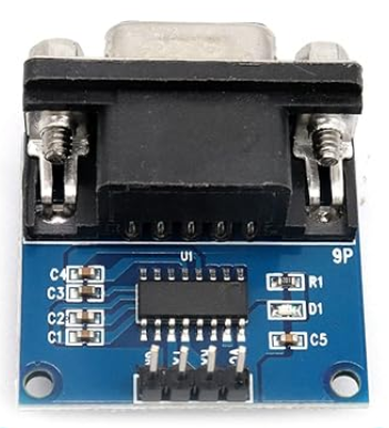
Pin Configuration and Descriptions
The pinout of the Convertitore_RS232 may vary slightly depending on the specific model. Below is a typical pin configuration for a module that converts RS-232 to TTL:
| Pin | Name | Description |
|---|---|---|
| 1 | Vcc | Power supply input (3.3V or 5V, depending on the module). |
| 2 | GND | Ground connection. |
| 3 | TXD (TTL) | Transmit data (TTL level). Connect to RX pin of the microcontroller. |
| 4 | RXD (TTL) | Receive data (TTL level). Connect to TX pin of the microcontroller. |
| 5 | TXD (RS-232) | Transmit data (RS-232 level). Connect to RX pin of the RS-232 device. |
| 6 | RXD (RS-232) | Receive data (RS-232 level). Connect to TX pin of the RS-232 device. |
| 7 | RTS (Optional) | Request to Send signal (RS-232 level). |
| 8 | CTS (Optional) | Clear to Send signal (RS-232 level). |
Usage Instructions
How to Use the Convertitore_RS232 in a Circuit
- Power the Module: Connect the Vcc pin to a 3.3V or 5V power source, depending on the module's specifications. Connect the GND pin to the ground of your circuit.
- Connect RS-232 Device: Attach the RS-232 device's TX and RX pins to the corresponding TXD (RS-232) and RXD (RS-232) pins on the module.
- Connect TTL Device: Connect the TTL device's TX and RX pins to the RXD (TTL) and TXD (TTL) pins on the module, respectively.
- Verify Connections: Ensure all connections are secure and that the voltage levels are compatible with the devices being interfaced.
- Test Communication: Use a terminal program or microcontroller code to test the communication between the devices.
Important Considerations and Best Practices
- Voltage Compatibility: Ensure the module's Vcc matches the voltage level of the TTL device (3.3V or 5V).
- Baud Rate Matching: Both devices must operate at the same baud rate for successful communication.
- Signal Integrity: Use short, high-quality cables to minimize noise and signal degradation, especially for RS-232 connections.
- Flow Control: If your application requires hardware flow control, ensure the RTS and CTS pins are properly connected and configured.
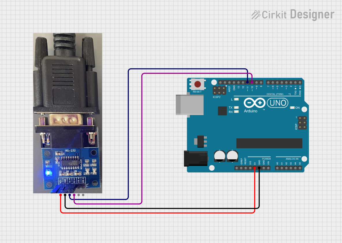
Example: Connecting to an Arduino UNO
Below is an example of how to use the Convertitore_RS232 to interface an RS-232 device with an Arduino UNO.
Circuit Diagram
- Connect the module's Vcc to the Arduino's 5V pin.
- Connect the module's GND to the Arduino's GND pin.
- Connect the module's RXD (TTL) to the Arduino's TX (pin 1).
- Connect the module's TXD (TTL) to the Arduino's RX (pin 0).
- Connect the RS-232 device to the module's TXD (RS-232) and RXD (RS-232) pins.
Arduino Code
// Example code for Arduino UNO to communicate with an RS-232 device
// Ensure the baud rate matches the RS-232 device's settings

void setup() {
  Serial.begin(9600); // Initialize serial communication at 9600 bps
  Serial.println("RS-232 Communication Initialized");
}

void loop() {
  // Check if data is available from the RS-232 device
  if (Serial.available() > 0) {
    char receivedChar = Serial.read(); // Read a character from the RS-232 device
    Serial.print("Received: ");
    Serial.println(receivedChar); // Print the received character to the Serial Monitor
  }

  // Send data to the RS-232 device
  Serial.println("Hello RS-232 Device!"); // Send a test message
  delay(1000); // Wait for 1 second before sending the next message
}
Troubleshooting and FAQs
Common Issues and Solutions
No Communication Between Devices
- Cause: Incorrect wiring or mismatched baud rates.
- Solution: Double-check all connections and ensure both devices are set to the same baud rate.
Data Corruption or Noise
- Cause: Long or poor-quality cables causing signal degradation.
- Solution: Use shorter, shielded cables and ensure proper grounding.
Module Not Powering On
- Cause: Incorrect voltage supplied to the Vcc pin.
- Solution: Verify the module's voltage requirements and ensure the power source matches.
Flow Control Issues
- Cause: RTS/CTS pins not connected or configured properly.
- Solution: If hardware flow control is required, ensure the RTS and CTS pins are connected and enabled in the software.
FAQs
Q: Can the Convertitore_RS232 be used with USB devices?
A: Some models include USB support, allowing RS-232 to USB conversion. Check the module's specifications to confirm compatibility.
Q: What is the maximum cable length for RS-232 communication?
A: RS-232 supports cable lengths up to 15 meters (50 feet) at lower baud rates. For higher baud rates, shorter cables are recommended.
Q: Can I use the Convertitore_RS232 with a 3.3V microcontroller?
A: Yes, as long as the module supports 3.3V operation. Verify the module's Vcc requirements before connecting.
Q: How do I test the module?
A: Use a loopback test by connecting the TXD (RS-232) pin to the RXD (RS-232) pin and sending data. If the data is received correctly, the module is functioning properly.