Cirkit Designer
Your all-in-one circuit design IDE
Home /
Component Documentation
How to Use rtd and data logger: Examples, Pinouts, and Specs
Introduction
- An RTD (Resistance Temperature Detector) is a temperature sensor that measures temperature by correlating the resistance of the RTD element with temperature. RTDs are known for their accuracy, stability, and repeatability.
- A data logger is an electronic device used to record data over time, often in conjunction with sensors like RTDs. It stores temperature readings for later analysis.
- This documentation focuses on integrating an RTD with a data logger for temperature monitoring and recording applications.
Explore Projects Built with rtd and data logger
Solar-Powered Arduino Weather Station with Data Logging

This circuit is designed for environmental data logging, powered by a solar panel and a lithium-ion battery through a charge controller. It uses an Arduino Nano to collect temperature, humidity, and pressure data from a DHT22 sensor and a BMP280 sensor, respectively. The data is logged to an SD card with timestamps from a DS3231 RTC module, and the system is programmed to log data every minute.
Solar-Powered Environmental Monitoring Station with Data Logging and Remote Access
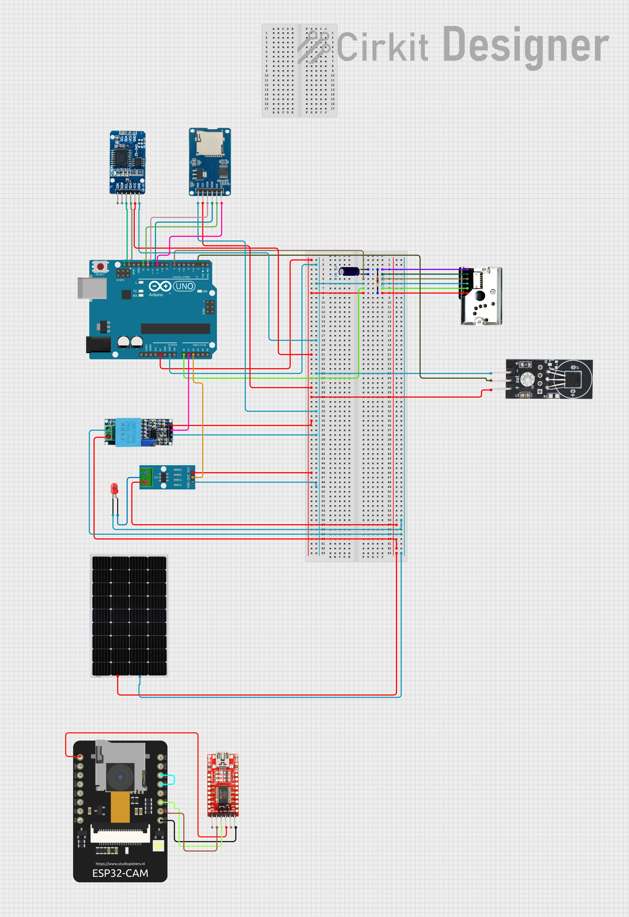
This circuit is a multi-sensor data logger with image capture capability, interfacing dust, temperature, current, and voltage sensors with an Arduino UNO for environmental monitoring. It includes an RTC for time-stamping, a micro SD card for data storage, and an ESP32 CAM module for image capture, programmed via an FTDI programmer.
Arduino UNO Data Logger with RTC and Micro SD Card Module
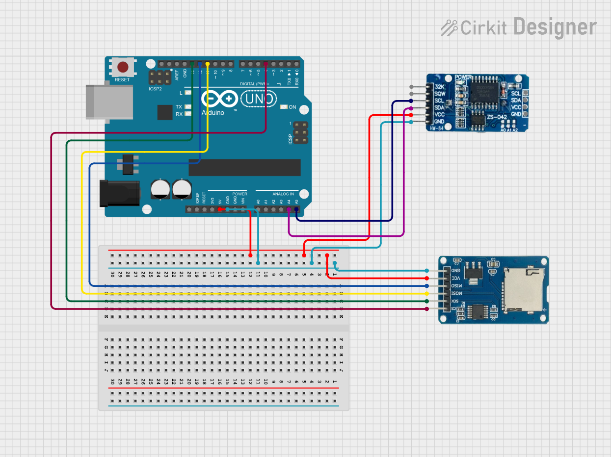
This circuit is a data logging system that uses an Arduino UNO to read time and date information from an RTC DS3231 module and store it on a Micro SD Card Module. The Arduino communicates with the RTC via I2C and with the SD card via SPI, logging the data every 5 seconds.
ESP32-Based Environmental Monitoring Station with CO2, Temperature, Humidity Sensing and Data Logging
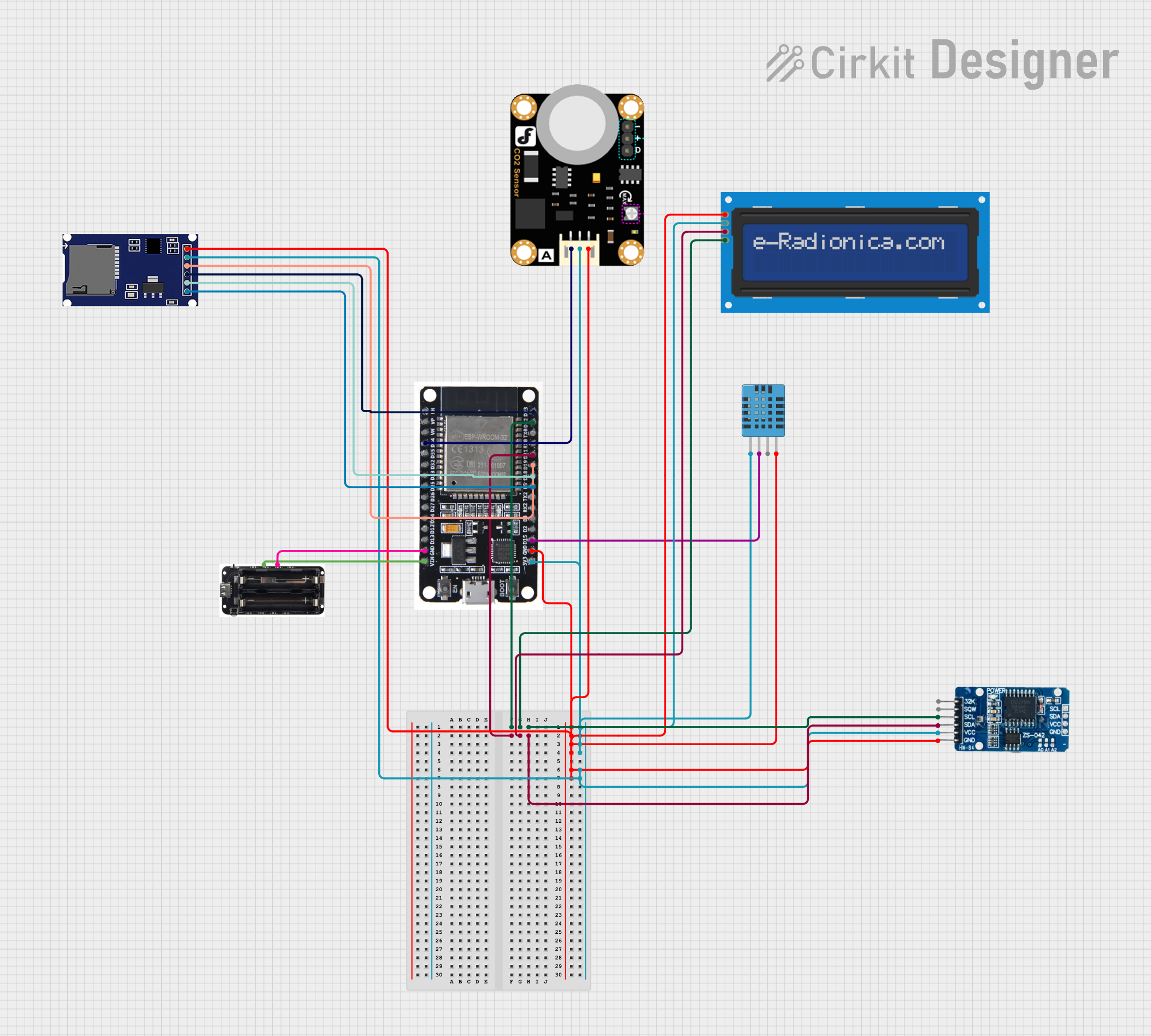
This is a multi-sensor data logging system with an ESP32 microcontroller that measures environmental parameters such as humidity, temperature, and CO2 levels. It includes an LCD for data display, an RTC for timekeeping, and an SD card module for data storage, all powered by a 18650 battery shield.
Explore Projects Built with rtd and data logger
Solar-Powered Arduino Weather Station with Data Logging
This circuit is designed for environmental data logging, powered by a solar panel and a lithium-ion battery through a charge controller. It uses an Arduino Nano to collect temperature, humidity, and pressure data from a DHT22 sensor and a BMP280 sensor, respectively. The data is logged to an SD card with timestamps from a DS3231 RTC module, and the system is programmed to log data every minute.
Solar-Powered Environmental Monitoring Station with Data Logging and Remote Access
This circuit is a multi-sensor data logger with image capture capability, interfacing dust, temperature, current, and voltage sensors with an Arduino UNO for environmental monitoring. It includes an RTC for time-stamping, a micro SD card for data storage, and an ESP32 CAM module for image capture, programmed via an FTDI programmer.
Arduino UNO Data Logger with RTC and Micro SD Card Module
This circuit is a data logging system that uses an Arduino UNO to read time and date information from an RTC DS3231 module and store it on a Micro SD Card Module. The Arduino communicates with the RTC via I2C and with the SD card via SPI, logging the data every 5 seconds.
ESP32-Based Environmental Monitoring Station with CO2, Temperature, Humidity Sensing and Data Logging
This is a multi-sensor data logging system with an ESP32 microcontroller that measures environmental parameters such as humidity, temperature, and CO2 levels. It includes an LCD for data display, an RTC for timekeeping, and an SD card module for data storage, all powered by a 18650 battery shield.
Common Applications and Use Cases
- Industrial process monitoring
- Environmental temperature tracking
- Laboratory experiments
- Food storage and transportation
- HVAC system diagnostics
Technical Specifications
RTD Specifications
| Parameter | Value/Description |
|---|---|
| Sensor Type | RTD (Resistance Temperature Detector) |
| Temperature Range | -200°C to 850°C |
| Accuracy | ±0.1°C to ±0.5°C (depending on model) |
| Resistance at 0°C | 100Ω (commonly PT100) |
| Material | Platinum |
| Response Time | 0.5 to 5 seconds (depending on design) |
Data Logger Specifications
| Parameter | Value/Description |
|---|---|
| Input Channels | 1 to 16 (depending on model) |
| Input Type | RTD, Thermocouple, Voltage, etc. |
| Sampling Rate | 1 Hz to 1 kHz |
| Storage Capacity | 1 MB to 32 GB |
| Communication Interface | USB, Wi-Fi, or Bluetooth |
| Power Supply | Battery or USB-powered |
Pin Configuration and Descriptions
RTD Pin Configuration
| Pin Number | Pin Name | Description |
|---|---|---|
| 1 | RTD+ | Positive terminal of the RTD sensor |
| 2 | RTD- | Negative terminal of the RTD sensor |
| 3 | Shield | Optional shield for noise reduction |
Data Logger Pin Configuration
| Pin Number | Pin Name | Description |
|---|---|---|
| 1 | VCC | Power supply (3.3V or 5V) |
| 2 | GND | Ground |
| 3 | CH1 | Input channel for RTD sensor |
| 4 | CH2 | Additional input channel (optional) |
| 5 | TX | Transmit data (for UART interface) |
| 6 | RX | Receive data (for UART interface) |
Usage Instructions
How to Use the Component in a Circuit
- Connect the RTD to the Data Logger:
- Connect the RTD+ pin to the CH1 input of the data logger.
- Connect the RTD- pin to the GND pin of the data logger.
- If available, connect the shield pin to the ground to reduce noise.
- Power the Data Logger:
- Supply power to the data logger using a 3.3V or 5V source, depending on the model.
- Configure the Data Logger:
- Use the manufacturer's software or interface to set the sampling rate, temperature range, and storage interval.
- Start Logging:
- Begin recording data by pressing the start button or sending a command via the communication interface.
Important Considerations and Best Practices
- Calibration: Ensure the RTD is properly calibrated for accurate temperature readings.
- Wiring: Use shielded cables for the RTD to minimize electrical noise.
- Environment: Protect the RTD and data logger from extreme environmental conditions (e.g., moisture, dust).
- Power Supply: Use a stable power source to avoid interruptions in data logging.
- Data Backup: Regularly transfer logged data to a computer or cloud storage to prevent data loss.
Arduino UNO Example Code
Below is an example of how to interface an RTD and data logger with an Arduino UNO:
#include <Wire.h>  // Include Wire library for I2C communication
#include <Adafruit_MAX31865.h>  // Include library for RTD (e.g., PT100)

// Define pins for the RTD (using MAX31865 breakout board)
#define RTD_CS_PIN 10  // Chip Select pin
#define RTD_MOSI_PIN 11  // Master Out Slave In pin
#define RTD_MISO_PIN 12  // Master In Slave Out pin
#define RTD_SCK_PIN 13  // Serial Clock pin

// Create an instance of the MAX31865 library
Adafruit_MAX31865 rtd = Adafruit_MAX31865(RTD_CS_PIN, RTD_MOSI_PIN, RTD_MISO_PIN, RTD_SCK_PIN);

void setup() {
  Serial.begin(9600);  // Start serial communication
  Serial.println("RTD and Data Logger Example");

  // Initialize the RTD sensor
  if (!rtd.begin(MAX31865_3WIRE)) {  // Use 3-wire RTD configuration
    Serial.println("RTD initialization failed!");
    while (1);  // Halt execution if initialization fails
  }
}

void loop() {
  // Read temperature from the RTD
  float temperature = rtd.temperature(100.0, 430.0);  // PT100 with 430Ω reference resistor

  // Print temperature to the serial monitor
  Serial.print("Temperature: ");
  Serial.print(temperature);
  Serial.println(" °C");

  // Add code here to log data to the data logger
  // For example, send data via UART or store it in an SD card

  delay(1000);  // Wait 1 second before the next reading
}
Troubleshooting and FAQs
Common Issues and Solutions
RTD Not Reading Correctly:
- Cause: Loose or incorrect wiring.
- Solution: Double-check all connections and ensure proper pin mapping.
Data Logger Not Storing Data:
- Cause: Insufficient storage or incorrect configuration.
- Solution: Clear storage or reconfigure the data logger settings.
Noisy Temperature Readings:
- Cause: Electrical interference or poor shielding.
- Solution: Use shielded cables and ensure proper grounding.
Arduino Fails to Communicate with RTD:
- Cause: Incorrect SPI pin configuration.
- Solution: Verify the SPI pin assignments in the code.
FAQs
Q: Can I use a 2-wire RTD with this setup?
- A: Yes, but 3-wire or 4-wire RTDs are recommended for better accuracy.
Q: How do I transfer data from the logger to a computer?
- A: Use the communication interface (e.g., USB, Wi-Fi) provided by the data logger.
Q: What is the maximum cable length for the RTD?
- A: Typically up to 100 meters with proper shielding, but this depends on the RTD and environment.
Q: Can I use this setup for high-temperature applications?
- A: Yes, as long as the RTD and data logger are rated for the required temperature range.