How to Use LM124: Examples, Pinouts, and Specs
Introduction
The LM124 is a quad operational amplifier (op-amp) manufactured by Texas Instruments, with the part ID LM124DR. This component is designed for a wide range of applications, including signal conditioning, filtering, and amplification. It features low noise, high gain, and excellent stability, making it a reliable choice for both analog and mixed-signal designs. The LM124 operates over a wide voltage range and is suitable for use in industrial, automotive, and consumer electronics.
Explore Projects Built with LM124


Explore Projects Built with LM124
Common Applications
- Signal amplification in audio and sensor circuits
- Active filters for signal processing
- Voltage comparators
- Analog computation circuits
- Data acquisition systems
Technical Specifications
Key Specifications
| Parameter | Value |
|---|---|
| Supply Voltage Range | ±1.5V to ±16V (dual supply) |
| Input Offset Voltage | 2 mV (typical) |
| Input Bias Current | 20 nA (typical) |
| Gain Bandwidth Product | 1 MHz |
| Slew Rate | 0.5 V/µs |
| Operating Temperature Range | -40°C to +85°C |
| Output Current | 20 mA (maximum) |
| Package Type | SOIC-14 (LM124DR) |
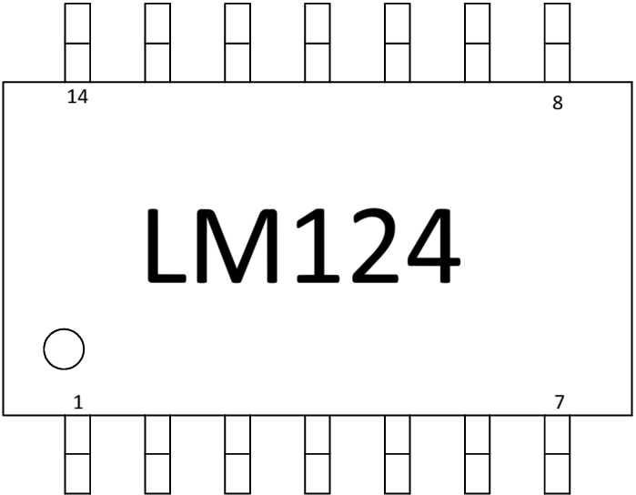
Pin Configuration and Descriptions
The LM124 is available in a 14-pin SOIC package. The pinout and descriptions are as follows:
| Pin Number | Pin Name | Description |
|---|---|---|
| 1 | Output 1 | Output of op-amp 1 |
| 2 | Inverting Input 1 | Inverting input of op-amp 1 |
| 3 | Non-Inverting Input 1 | Non-inverting input of op-amp 1 |
| 4 | VCC- (GND) | Negative power supply or ground |
| 5 | Non-Inverting Input 2 | Non-inverting input of op-amp 2 |
| 6 | Inverting Input 2 | Inverting input of op-amp 2 |
| 7 | Output 2 | Output of op-amp 2 |
| 8 | Output 3 | Output of op-amp 3 |
| 9 | Inverting Input 3 | Inverting input of op-amp 3 |
| 10 | Non-Inverting Input 3 | Non-inverting input of op-amp 3 |
| 11 | VCC+ | Positive power supply |
| 12 | Non-Inverting Input 4 | Non-inverting input of op-amp 4 |
| 13 | Inverting Input 4 | Inverting input of op-amp 4 |
| 14 | Output 4 | Output of op-amp 4 |
Usage Instructions
Using the LM124 in a Circuit
- Power Supply: Connect the LM124 to a dual power supply (e.g., ±12V) or a single supply (e.g., 5V to 32V). Pin 4 (VCC-) is connected to the negative supply or ground, and Pin 11 (VCC+) is connected to the positive supply.
- Input Connections: Use the inverting and non-inverting inputs of each op-amp (Pins 2, 3, 5, 6, 9, 10, 12, and 13) to configure the desired circuit (e.g., amplifier, comparator, or filter).
- Output Connections: Connect the outputs (Pins 1, 7, 8, and 14) to the load or next stage of the circuit.
- Feedback Network: Add resistors, capacitors, or other components between the output and input pins to set the gain, bandwidth, or other parameters of the circuit.
Important Considerations
- Input Voltage Range: Ensure the input voltage stays within the specified range to avoid saturation or damage.
- Bypass Capacitors: Place decoupling capacitors (e.g., 0.1 µF) close to the power supply pins to reduce noise and improve stability.
- Thermal Management: Operate the LM124 within the specified temperature range to ensure reliable performance.
- Unused Op-Amps: If any of the four op-amps are unused, configure them as voltage followers (connect the output to the inverting input and the non-inverting input to ground) to prevent oscillation.
Example: Connecting LM124 to an Arduino UNO
The LM124 can be used to amplify an analog signal before feeding it into an Arduino UNO's analog input. Below is an example of a non-inverting amplifier circuit with a gain of 10.
Circuit Configuration
- Connect Pin 11 (VCC+) to +5V and Pin 4 (VCC-) to GND.
- Connect the input signal to Pin 3 (Non-Inverting Input 1).
- Use a resistor divider for feedback: connect a 10 kΩ resistor between Pin 1 (Output 1) and Pin 2 (Inverting Input 1), and a 1 kΩ resistor between Pin 2 and GND.
- Connect Pin 1 to the Arduino UNO's analog input (e.g., A0).
Arduino Code
// Arduino code to read the amplified signal from the LM124
const int analogPin = A0; // Analog pin connected to LM124 output
int sensorValue = 0;      // Variable to store the analog reading

void setup() {
  Serial.begin(9600); // Initialize serial communication at 9600 baud
}

void loop() {
  sensorValue = analogRead(analogPin); // Read the analog value
  float voltage = sensorValue * (5.0 / 1023.0); // Convert to voltage
  Serial.print("Voltage: ");
  Serial.print(voltage);
  Serial.println(" V");
  delay(500); // Wait for 500 ms before the next reading
}
Troubleshooting and FAQs
Common Issues
No Output Signal:
- Check the power supply connections (Pins 4 and 11).
- Verify that the input signal is within the specified range.
- Ensure the feedback network is correctly configured.
Output Saturation:
- Ensure the input signal is not exceeding the op-amp's input voltage range.
- Check the gain configuration and reduce it if necessary.
Oscillation or Noise:
- Add bypass capacitors near the power supply pins.
- Verify that unused op-amps are properly terminated.
Overheating:
- Ensure the LM124 is operating within the specified voltage and temperature ranges.
- Check for excessive current draw on the output pins.
FAQs
Q: Can the LM124 operate with a single power supply?
A: Yes, the LM124 can operate with a single supply voltage ranging from 3V to 32V. Ensure the input signal is biased appropriately.
Q: What is the maximum output current of the LM124?
A: The maximum output current is 20 mA. Exceeding this limit may damage the device.
Q: How do I handle unused op-amps in the LM124?
A: Configure unused op-amps as voltage followers by connecting the output to the inverting input and the non-inverting input to ground.
Q: Is the LM124 suitable for audio applications?
A: Yes, the LM124's low noise and high gain make it suitable for audio signal amplification and processing.