How to Use relay 12v: Examples, Pinouts, and Specs
Introduction
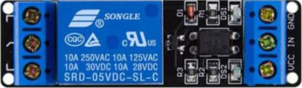
A 12V relay is an electrically operated switch that uses a 12-volt power supply to control a high-power circuit with a low-power signal. This component is widely used in various applications, including home automation, industrial control systems, and automotive electronics. By isolating the control circuit from the high-power circuit, relays provide a safe and efficient way to manage electrical loads.
Explore Projects Built with relay 12v


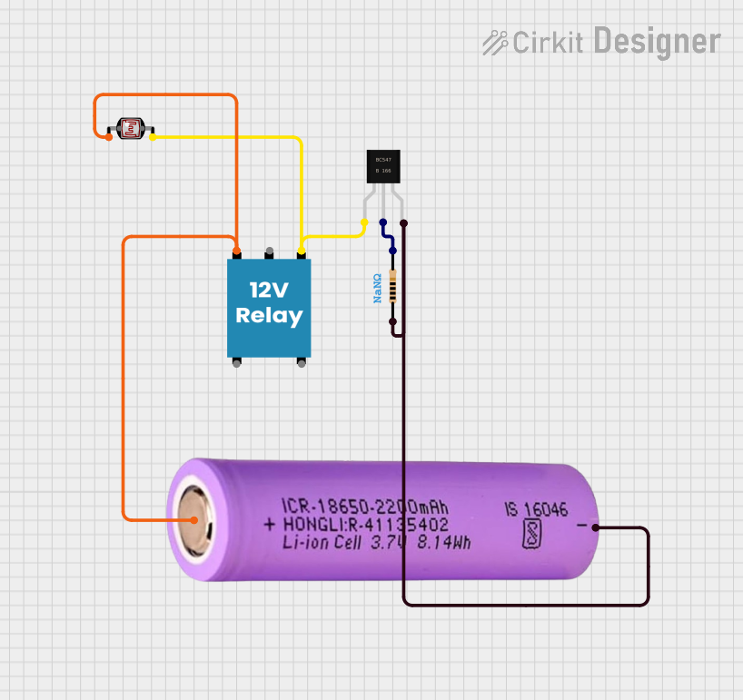
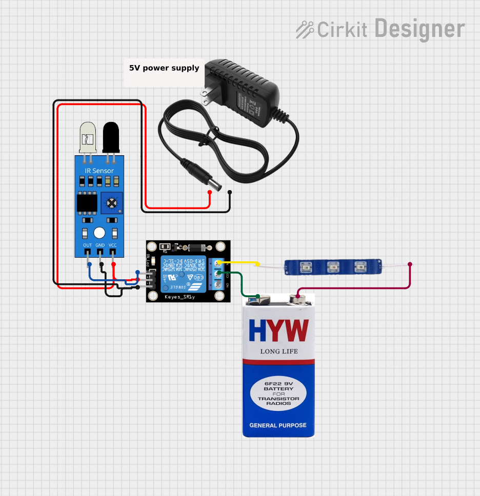
Explore Projects Built with relay 12v
Technical Specifications
Key Technical Details
| Parameter | Value |
|---|---|
| Operating Voltage | 12V DC |
| Trigger Voltage | 5V DC (for control) |
| Current Rating | 10A @ 250V AC / 10A @ 30V DC |
| Contact Type | SPDT (Single Pole Double Throw) |
| Coil Resistance | 400Ω |
| Switching Time | 10ms (operate), 5ms (release) |
| Dimensions | 19mm x 15.5mm x 15mm |
Pin Configuration and Descriptions
| Pin Number | Pin Name | Description |
|---|---|---|
| 1 | NO | Normally Open contact |
| 2 | COM | Common contact |
| 3 | NC | Normally Closed contact |
| 4 | VCC | 12V DC power supply for the relay coil |
| 5 | GND | Ground |
| 6 | IN | Control signal input (typically 5V from a microcontroller) |
Usage Instructions
How to Use the Component in a Circuit
Power Supply:
- Connect the VCC pin to a 12V DC power supply.
- Connect the GND pin to the ground of the power supply.
Control Signal:
- Connect the IN pin to a digital output pin of a microcontroller (e.g., Arduino UNO).
Load Connection:
- Connect the high-power circuit to the COM and NO/NC pins based on the desired operation:
- NO (Normally Open): The circuit is open when the relay is not energized.
- NC (Normally Closed): The circuit is closed when the relay is not energized.
- Connect the high-power circuit to the COM and NO/NC pins based on the desired operation:
Important Considerations and Best Practices
- Isolation: Ensure proper isolation between the control and high-power circuits to prevent damage to the microcontroller.
- Flyback Diode: Use a flyback diode across the relay coil to protect against voltage spikes.
- Current Rating: Do not exceed the current rating of the relay contacts to avoid damage.
- Heat Dissipation: Ensure adequate ventilation or heat sinking if the relay operates at high currents for extended periods.
Example Circuit with Arduino UNO
/*
 * Example code to control a 12V relay with an Arduino UNO.
 * The relay is connected to digital pin 7.
 */

const int relayPin = 7; // Define the relay control pin

void setup() {
  pinMode(relayPin, OUTPUT); // Set the relay pin as an output
  digitalWrite(relayPin, LOW); // Initialize the relay as off
}

void loop() {
  digitalWrite(relayPin, HIGH); // Turn the relay on
  delay(1000); // Wait for 1 second
  digitalWrite(relayPin, LOW); // Turn the relay off
  delay(1000); // Wait for 1 second
}
Troubleshooting and FAQs
Common Issues Users Might Face
Relay Not Switching:
- Solution: Ensure the control signal voltage is sufficient (typically 5V for the IN pin). Check the power supply voltage (12V) and connections.
Chattering or Buzzing:
- Solution: Verify the power supply is stable and capable of providing the required current. Check for loose connections.
Overheating:
- Solution: Ensure the relay is not exceeding its current rating. Provide adequate ventilation or heat sinking.
No Response from Load:
- Solution: Check the wiring of the load circuit. Ensure the load is connected to the correct relay contacts (COM and NO/NC).
FAQs
Q: Can I use a 12V relay with a 5V microcontroller?
- A: Yes, the control signal (IN pin) typically operates at 5V, but the relay coil requires a 12V power supply.
Q: What is the purpose of a flyback diode?
- A: A flyback diode protects the circuit from voltage spikes generated when the relay coil is de-energized.
Q: Can I control multiple relays with a single microcontroller?
- A: Yes, you can control multiple relays using different digital output pins on the microcontroller.
By following this documentation, users can effectively integrate a 12V relay into their projects, ensuring safe and reliable operation.