How to Use CCS811 Air Quality Sensor Module: Examples, Pinouts, and Specs
Introduction
The CCS811 Air Quality Sensor Module is a digital gas sensor solution that detects a wide range of Volatile Organic Compounds (VOCs) and carbon monoxide (CO) in real-time. This sensor is designed for indoor air quality monitoring and can be used in various applications such as smart homes, HVAC systems, and air purifiers. It utilizes a micro-hotplate technology and a metal oxide (MOX) sensor, providing a reliable measurement of air contaminants.
Explore Projects Built with CCS811 Air Quality Sensor Module
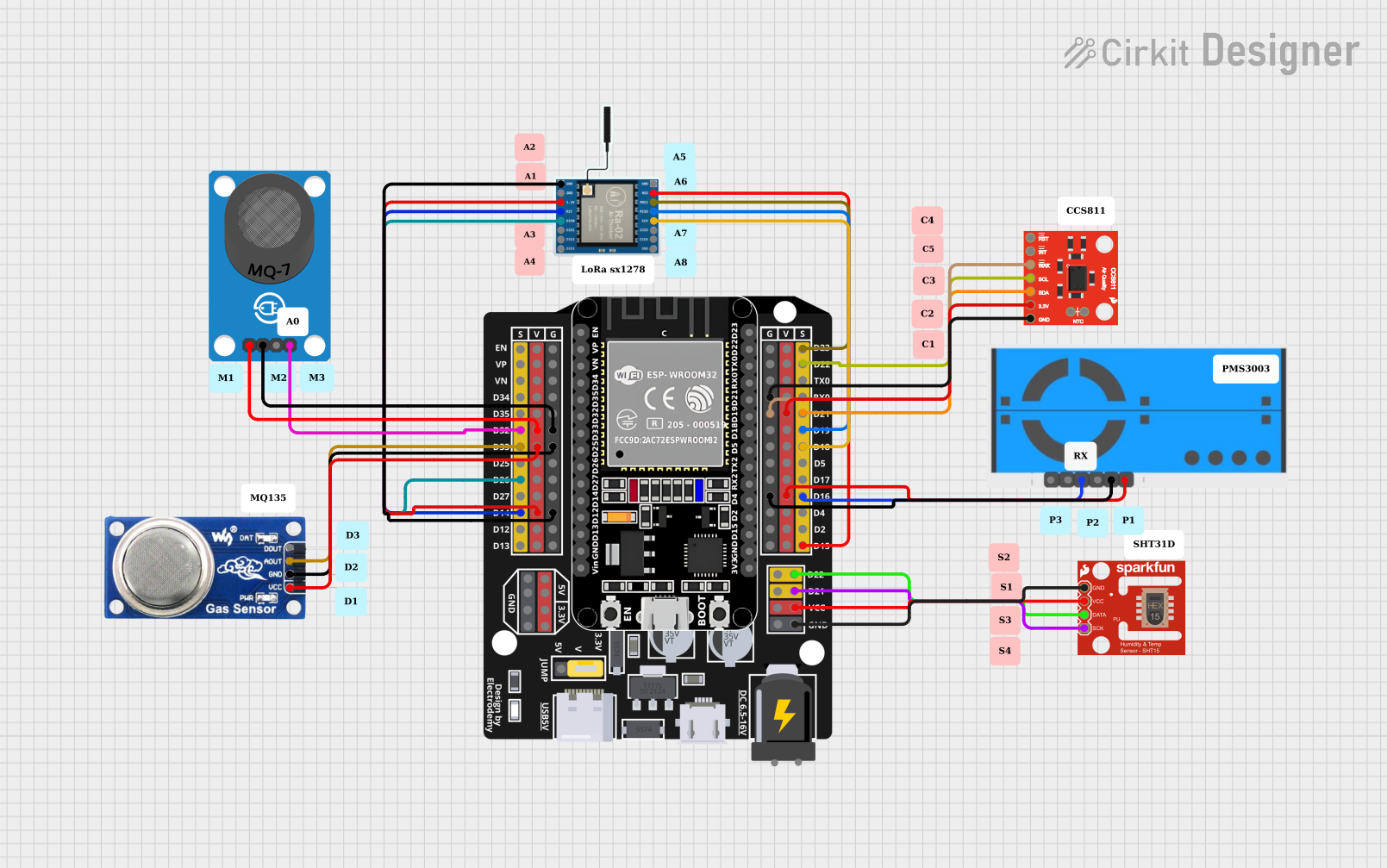
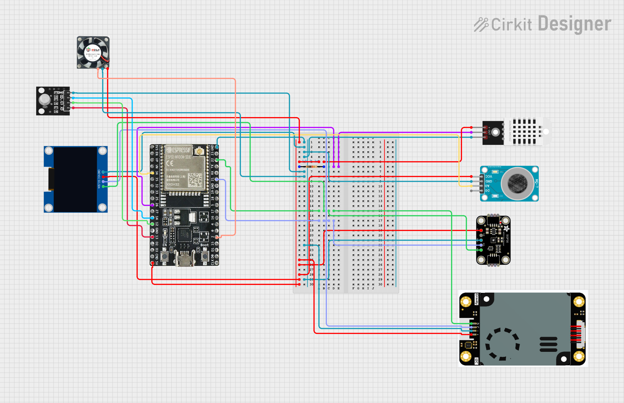
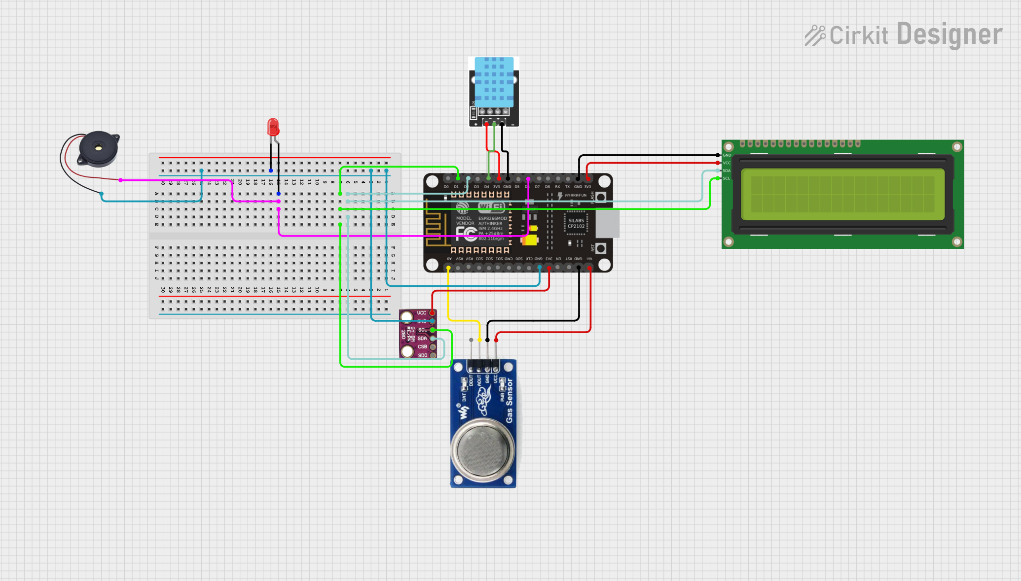
Explore Projects Built with CCS811 Air Quality Sensor Module
Technical Specifications
Key Technical Details
- Measurement Range (CO2): 400 to 8192 ppm
- Measurement Range (TVOC): 0 to 1187 ppb
- Interface: I2C
- Supply Voltage: 3.3V
- Current Consumption: 60 mA during measurement, 10 µA in sleep mode
- Operating Temperature: -40°C to 85°C
- Humidity Range: 10% to 95% relative humidity, non-condensing
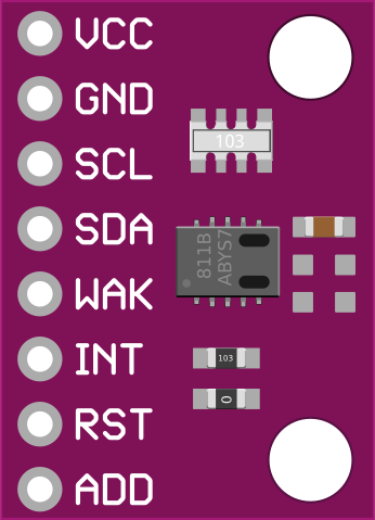
Pin Configuration and Descriptions
| Pin Number | Pin Name | Description |
|---|---|---|
| 1 | VDD | Supply voltage (3.3V) |
| 2 | GND | Ground |
| 3 | SDA | Serial Data Line for I2C communication |
| 4 | SCL | Serial Clock Line for I2C communication |
| 5 | WAKE | Wake pin, active low |
| 6 | INT | Interrupt pin, active low |
| 7 | RST | Reset pin, active low |
| 8 | ADDR | I2C address selection pin |
Usage Instructions
Integration with a Circuit
- Power Supply: Connect the VDD pin to a 3.3V source and the GND pin to ground.
- I2C Communication: Connect the SDA and SCL pins to the corresponding SDA and SCL pins on your microcontroller (e.g., Arduino UNO).
- Wake and Reset: The WAKE pin should be connected to ground to keep the sensor awake. The RST pin can be left unconnected if not used.
- Interrupts (Optional): The INT pin can be connected to an interrupt-capable GPIO pin on your microcontroller if you wish to use the interrupt feature.
- Address Selection: The ADDR pin can be connected to ground or VDD to change the I2C address if multiple I2C devices are used.
Best Practices
- Ensure that the sensor is preheated for at least 20 minutes before taking measurements for the first time.
- Avoid placing the sensor in environments with high concentrations of corrosive gases.
- Keep the sensor away from direct sunlight and high humidity conditions.
- Use pull-up resistors on the I2C lines if your microcontroller does not have built-in pull-ups.
Example Code for Arduino UNO
#include <Wire.h>
#include "Adafruit_CCS811.h"

Adafruit_CCS811 ccs;

void setup() {
  Serial.begin(9600);
  Wire.begin();

  // Initialize the CCS811 sensor
  if (!ccs.begin()) {
    Serial.println("Failed to start sensor! Please check your wiring.");
    while (1);
  }

  // Wait for the sensor to be ready
  while (!ccs.available());
}

void loop() {
  // Check if data is available to read
  if (ccs.available()) {
    // Read sensor data
    if (!ccs.readData()) {
      // Output the CO2 and TVOC readings
      Serial.print("CO2: ");
      Serial.print(ccs.geteCO2());
      Serial.print("ppm, TVOC: ");
      Serial.print(ccs.getTVOC());
      Serial.println("ppb");
    } else {
      Serial.println("ERROR! Unable to read sensor data.");
    }
  }
  delay(500); // Wait for 500 milliseconds before next read
}
Troubleshooting and FAQs
Common Issues
- Sensor not responding: Ensure that the sensor is correctly powered and that the I2C connections are secure. Check for proper pull-up resistors on the I2C lines.
- Inaccurate readings: Verify that the sensor has been preheated and calibrated if necessary. Avoid exposing the sensor to pollutants that can cause sensor drift.
- High power consumption in sleep mode: Make sure that the WAKE pin is correctly managed to allow the sensor to enter sleep mode.
Solutions and Tips
- Preheating: Run the sensor for at least 20 minutes before taking the first reading.
- Calibration: Follow the manufacturer's guidelines for calibration, which may include exposing the sensor to clean air.
- Sensor Placement: Install the sensor in a location with good air circulation and away from direct heat sources.
FAQs
Q: Can the CCS811 sensor measure CO2 directly? A: No, the CCS811 sensor estimates CO2 levels based on the detected VOCs. It is not a direct CO2 sensor.
Q: How often should the sensor be calibrated? A: The sensor should be calibrated according to the manufacturer's recommendations or when there is a significant change in the operating environment.
Q: What is the lifespan of the CCS811 sensor? A: The typical lifespan of the CCS811 sensor is around five years, depending on the operating conditions and usage.
Q: Can the sensor operate at 5V? A: No, the CCS811 is designed to operate at 3.3V. Using a higher voltage can damage the sensor.