
How to Use SmartSolar MPPT RS 450|200 MC4: Examples, Pinouts, and Specs
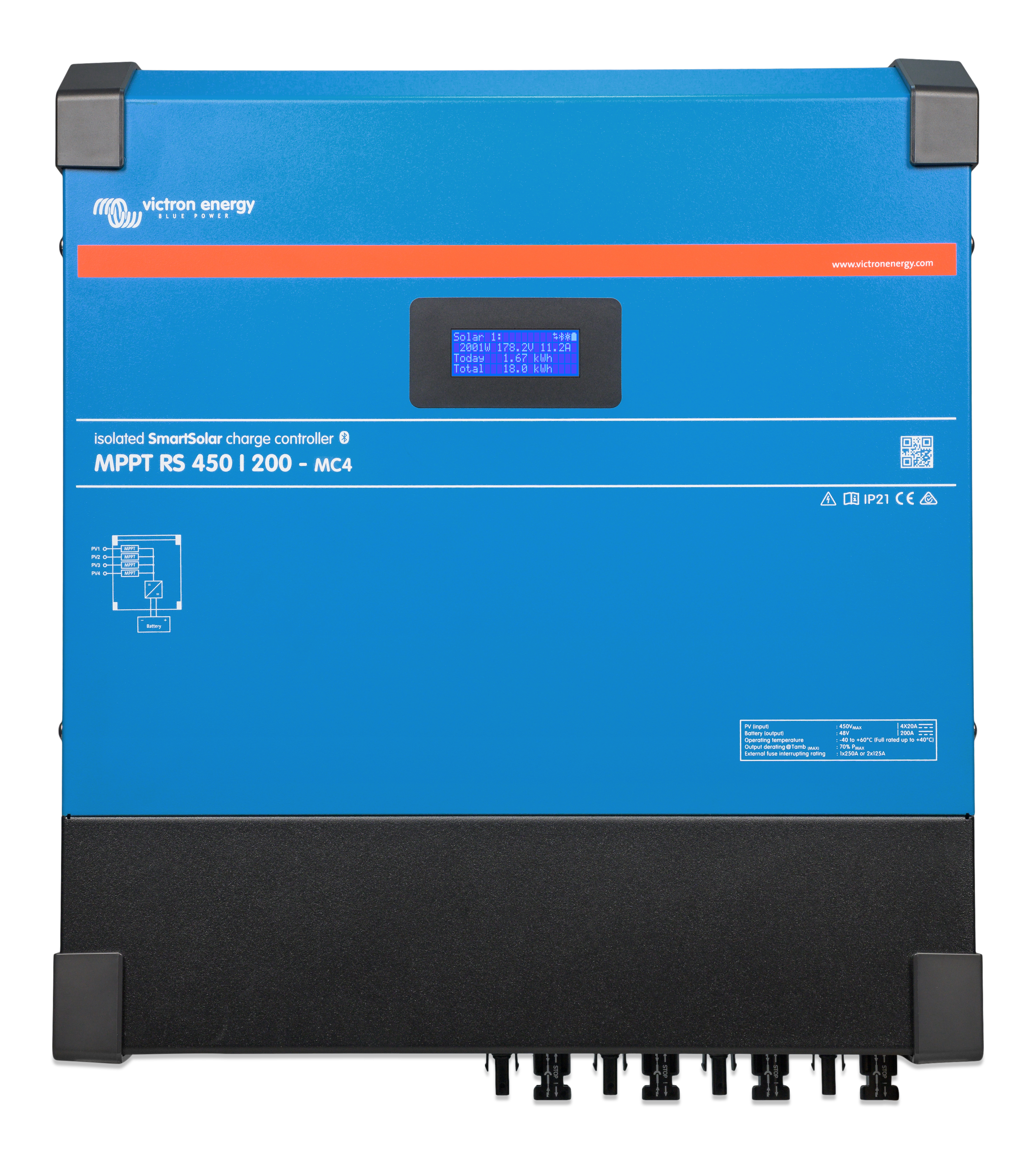
 Design with SmartSolar MPPT RS 450|200 MC4 in Cirkit Designer
Introduction
The SmartSolar MPPT RS 450|200 MC4 is a high-performance solar charge controller manufactured by Victron Energy. It utilizes advanced Maximum Power Point Tracking (MPPT) technology to maximize energy harvest from solar panels, ensuring optimal efficiency even in challenging conditions such as partial shading or varying sunlight. This controller is specifically designed for large off-grid solar systems and is capable of handling high input voltages and currents, making it ideal for industrial, commercial, and residential solar installations.
Explore Projects Built with SmartSolar MPPT RS 450|200 MC4
 Open Project in Cirkit Designer
 Open Project in Cirkit Designer
 Open Project in Cirkit Designer
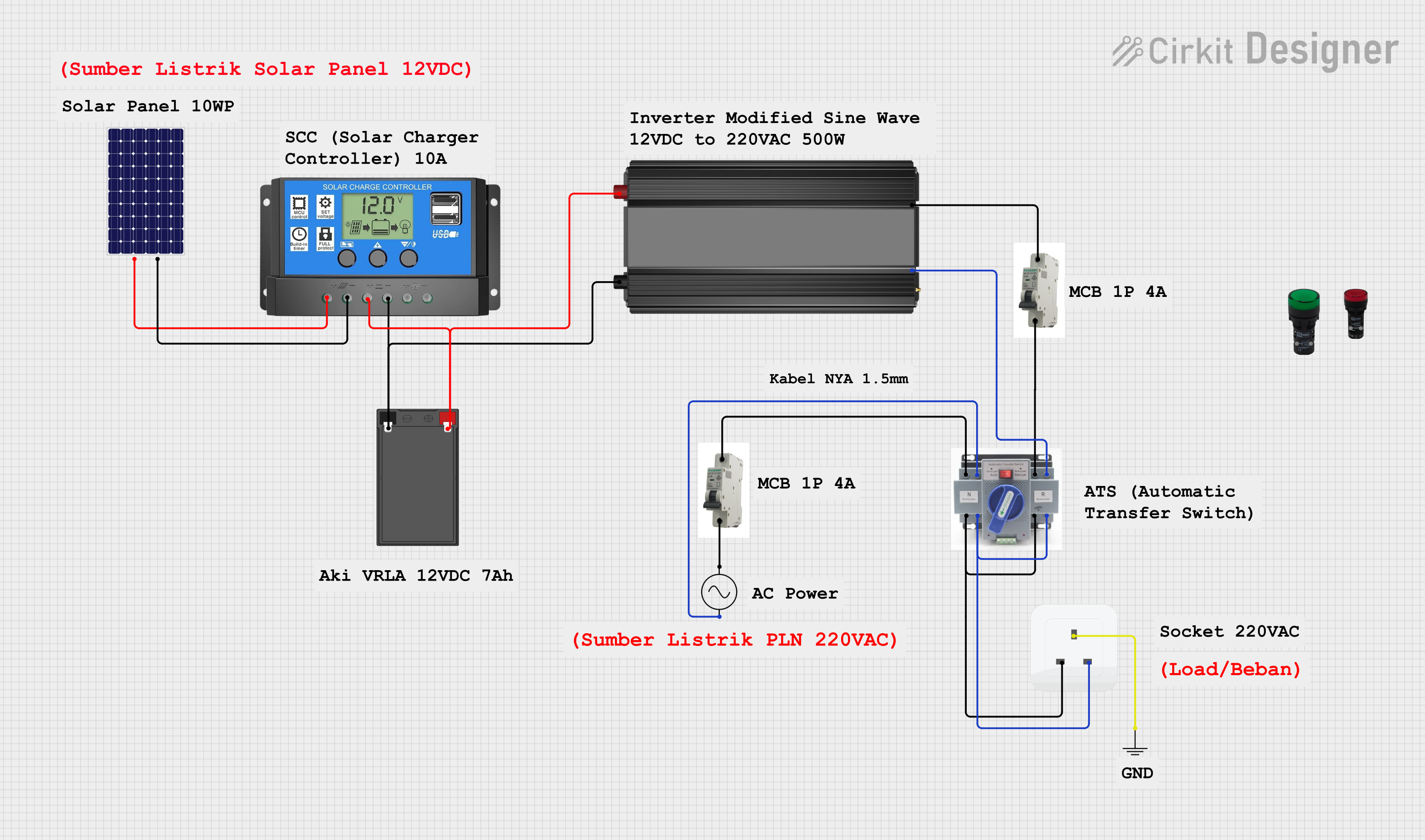 Open Project in Cirkit Designer
Explore Projects Built with SmartSolar MPPT RS 450|200 MC4
Open Project in Cirkit DesignerOpen Project in Cirkit DesignerOpen Project in Cirkit DesignerOpen Project in Cirkit DesignerCommon Applications and Use Cases
- Off-grid solar power systems for homes, businesses, and remote locations
- Industrial solar installations requiring high power output
- Solar-powered telecommunications and data centers
- Renewable energy systems for agricultural applications
- Backup power systems with battery storage integration
Technical Specifications
Key Technical Details
| Parameter | Value |
|---|---|
| Manufacturer | Victron Energy |
| Part ID | SCC145120510 |
| Input Voltage Range | Up to 450 VDC |
| Maximum PV Open Circuit Voltage (Voc) | 450 VDC |
| Maximum Charge Current | 200 A |
| Battery Voltage Range | 24 VDC / 48 VDC (auto-select) |
| Efficiency | Up to 98% |
| Communication Interfaces | VE.Can, VE.Direct, Bluetooth, RS485 |
| Operating Temperature Range | -40°C to +60°C (-40°F to +140°F) |
| Enclosure Rating | IP22 |
| Dimensions (H x W x D) | 425 x 350 x 125 mm |
| Weight | 11.9 kg |
Pin Configuration and Descriptions
The SmartSolar MPPT RS 450|200 MC4 features multiple connection points for PV input, battery output, and communication interfaces. Below is a summary of the key connections:
PV Input Terminals
| Pin Name | Description |
|---|---|
| PV+ | Positive terminal for solar panel input |
| PV- | Negative terminal for solar panel input |
Battery Output Terminals
| Pin Name | Description |
|---|---|
| BAT+ | Positive terminal for battery connection |
| BAT- | Negative terminal for battery connection |
Communication Ports
| Port Name | Description |
|---|---|
| VE.Can | CAN bus communication for system integration |
| VE.Direct | Direct communication with Victron devices |
| RS485 | Modbus communication for third-party integration |
| Bluetooth | Wireless monitoring and configuration |
Usage Instructions
How to Use the Component in a Circuit
Connect the Solar Panels:
- Ensure the total open-circuit voltage (Voc) of the solar array does not exceed 450 VDC.
- Use the MC4 connectors to securely attach the solar panel leads to the PV+ and PV- terminals.
Connect the Battery:
- Verify the battery voltage is within the supported range (24 VDC or 48 VDC).
- Connect the battery leads to the BAT+ and BAT- terminals, ensuring proper polarity.
Configure the System:
- Use the VictronConnect app (via Bluetooth) or a VE.Direct cable to configure the charge controller.
- Set the battery type (e.g., Lithium, AGM, Gel) and charge parameters as per the battery manufacturer's recommendations.
Monitor and Operate:
- Monitor real-time performance using the VictronConnect app or a GX device connected via VE.Can.
- Ensure the system is operating within the specified temperature and voltage ranges.
Important Considerations and Best Practices
- Safety First: Always disconnect the battery and solar panels before performing any wiring or maintenance.
- Proper Sizing: Ensure the solar array and battery bank are appropriately sized for the charge controller's capacity.
- Ventilation: Install the controller in a well-ventilated area to prevent overheating.
- Firmware Updates: Regularly check for firmware updates via the VictronConnect app to ensure optimal performance and compatibility.
Arduino Integration Example
While the SmartSolar MPPT RS 450|200 MC4 is not directly compatible with Arduino, it can communicate via the RS485 Modbus interface. Below is an example of how to read data from the charge controller using an Arduino and an RS485 module:
#include <ModbusMaster.h>

// Instantiate ModbusMaster object
ModbusMaster node;

// Define RS485 communication pins
#define RE_PIN 2  // Receiver Enable pin
#define DE_PIN 3  // Driver Enable pin

void preTransmission() {
  digitalWrite(RE_PIN, HIGH); // Enable transmission
  digitalWrite(DE_PIN, HIGH);
}

void postTransmission() {
  digitalWrite(RE_PIN, LOW);  // Disable transmission
  digitalWrite(DE_PIN, LOW);
}

void setup() {
  // Initialize serial communication
  Serial.begin(9600);
  Serial.println("Initializing RS485 Modbus communication...");

  // Initialize RS485 control pins
  pinMode(RE_PIN, OUTPUT);
  pinMode(DE_PIN, OUTPUT);
  postTransmission();

  // Configure Modbus communication
  node.begin(1, Serial); // Slave ID 1
  node.preTransmission(preTransmission);
  node.postTransmission(postTransmission);
}

void loop() {
  uint8_t result;
  uint16_t data;

  // Read battery voltage (example Modbus register address: 0x3100)
  result = node.readInputRegisters(0x3100, 1);
  if (result == node.ku8MBSuccess) {
    data = node.getResponseBuffer(0);
    Serial.print("Battery Voltage: ");
    Serial.print(data / 100.0); // Convert to volts
    Serial.println(" V");
  } else {
    Serial.println("Failed to read data from charge controller.");
  }

  delay(1000); // Wait 1 second before next read
}
Troubleshooting and FAQs
Common Issues and Solutions
No Output to Battery:
- Cause: Incorrect wiring or battery voltage out of range.
- Solution: Verify the battery connections and ensure the voltage matches the controller's supported range.
Low Efficiency or Energy Harvest:
- Cause: Shading on solar panels or incorrect MPPT settings.
- Solution: Ensure the solar panels are free from shading and check the MPPT configuration.
Overheating:
- Cause: Poor ventilation or excessive ambient temperature.
- Solution: Install the controller in a well-ventilated area and ensure the ambient temperature is within the operating range.
Bluetooth Connection Issues:
- Cause: Interference or outdated firmware.
- Solution: Move closer to the controller and update the firmware using the VictronConnect app.
FAQs
Q: Can I use this controller with a 12V battery system?
A: No, the SmartSolar MPPT RS 450|200 MC4 only supports 24V and 48V battery systems.Q: How do I update the firmware?
A: Use the VictronConnect app via Bluetooth or a VE.Direct cable to check for and install firmware updates.Q: Can I connect multiple charge controllers in parallel?
A: Yes, multiple controllers can be connected in parallel for larger systems, but ensure proper system design and configuration.Q: What is the maximum cable length for the RS485 connection?
A: The maximum recommended cable length for RS485 communication is 1,200 meters (4,000 feet).
This concludes the documentation for the SmartSolar MPPT RS 450|200 MC4. For further assistance, refer to the official Victron Energy user manual or contact their support team.