
How to Use POWER SUPPLY 5V 5AMP: Examples, Pinouts, and Specs
 Design with POWER SUPPLY 5V 5AMP in Cirkit Designer
Introduction
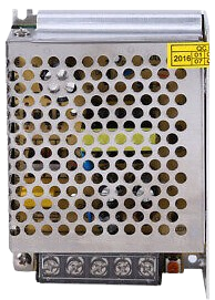
The POWER SUPPLY 5V 5AMP is a reliable and efficient power source designed to provide a stable output of 5 volts with a maximum current capacity of 5 amps. This component is ideal for powering a wide range of electronic devices, microcontrollers, sensors, and other circuits that require a steady 5V DC supply. Its robust design ensures consistent performance, making it suitable for both hobbyist projects and professional applications.
Explore Projects Built with POWER SUPPLY 5V 5AMP
 Open Project in Cirkit Designer
 Open Project in Cirkit Designer
 Open Project in Cirkit Designer
 Open Project in Cirkit Designer
Explore Projects Built with POWER SUPPLY 5V 5AMP
Open Project in Cirkit DesignerOpen Project in Cirkit DesignerOpen Project in Cirkit DesignerOpen Project in Cirkit DesignerCommon Applications and Use Cases
- Powering microcontrollers such as Arduino, Raspberry Pi, and ESP32.
- Driving LED strips, motors, and other high-current devices.
- Supplying power to sensors and modules in IoT projects.
- Bench power supply for prototyping and testing circuits.
- Replacement power supply for consumer electronics.
Technical Specifications
Below are the key technical details of the POWER SUPPLY 5V 5AMP:
| Parameter | Specification |
|---|---|
| Output Voltage | 5V DC |
| Maximum Output Current | 5A |
| Input Voltage Range | 100-240V AC, 50/60Hz |
| Efficiency | ≥85% |
| Ripple and Noise | ≤50mV |
| Operating Temperature | -10°C to +50°C |
| Protection Features | Overload, Overvoltage, Short Circuit |
Pin Configuration and Descriptions
The POWER SUPPLY 5V 5AMP typically has the following connections:
| Pin/Terminal | Description |
|---|---|
| AC Input (L) | Live wire connection for AC mains input |
| AC Input (N) | Neutral wire connection for AC mains |
| Ground (⏚) | Earth/ground connection for safety |
| DC Output (+) | Positive 5V DC output |
| DC Output (-) | Negative (ground) DC output |
Usage Instructions
How to Use the Component in a Circuit
Connect the AC Input:
- Ensure the power supply is disconnected from the mains before wiring.
- Connect the Live (L) and Neutral (N) terminals to the AC mains supply.
- Optionally, connect the Ground (⏚) terminal to the earth for safety.
Connect the DC Output:
- Use the DC Output (+) and (-) terminals to power your circuit.
- Ensure the connected load does not exceed the maximum current rating of 5A.
Power On:
- After all connections are secure, plug the power supply into the mains and switch it on.
- Verify the output voltage using a multimeter before connecting sensitive devices.
Important Considerations and Best Practices
- Load Requirements: Ensure the total current draw of your circuit does not exceed 5A to prevent overloading.
- Ventilation: Place the power supply in a well-ventilated area to avoid overheating.
- Polarity: Double-check the polarity of the DC output connections to prevent damage to your circuit.
- Safety Precautions: Always handle the AC input connections with care and ensure proper insulation to avoid electric shock.
Example: Using with Arduino UNO
The POWER SUPPLY 5V 5AMP can be used to power an Arduino UNO via its 5V pin. Below is an example of how to connect and use it:
- Connect the DC Output (+) terminal to the 5V pin of the Arduino UNO.
- Connect the DC Output (-) terminal to the GND pin of the Arduino UNO.
- Ensure the Arduino's total current consumption (including connected peripherals) does not exceed 5A.
Here is a simple Arduino sketch to blink an LED while powered by the power supply:
// Simple LED Blink Example
// This code assumes an LED is connected to pin 13 of the Arduino UNO.

void setup() {
  pinMode(13, OUTPUT); // Set pin 13 as an output
}

void loop() {
  digitalWrite(13, HIGH); // Turn the LED on
  delay(1000);            // Wait for 1 second
  digitalWrite(13, LOW);  // Turn the LED off
  delay(1000);            // Wait for 1 second
}
Troubleshooting and FAQs
Common Issues Users Might Face
No Output Voltage:
- Cause: AC input is not connected or switched off.
- Solution: Verify the AC input connections and ensure the mains power is on.
Overheating:
- Cause: Insufficient ventilation or excessive load.
- Solution: Ensure proper airflow around the power supply and reduce the load if necessary.
Device Not Powering On:
- Cause: Incorrect polarity or loose connections.
- Solution: Double-check the DC output connections and ensure correct polarity.
Frequent Shutdowns:
- Cause: Overload or short circuit protection is triggered.
- Solution: Reduce the load or check for short circuits in the connected circuit.
Solutions and Tips for Troubleshooting
- Use a multimeter to measure the output voltage and verify it is 5V.
- Inspect all connections for loose wires or poor contact.
- If the power supply fails to operate, check the fuse (if accessible) and replace it if blown.
- Avoid using the power supply in environments with high humidity or extreme temperatures.
By following these guidelines and best practices, the POWER SUPPLY 5V 5AMP can be a reliable and efficient power source for your electronic projects.