How to Use Delay Relay Shield NE555 Timer Switch Module 0-150 Second Adjustable DC 5-12V: Examples, Pinouts, and Specs
Introduction
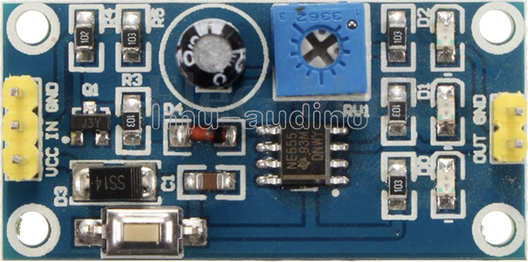
The Delay Relay Shield NE555 Timer Switch Module is a versatile timing module designed around the NE555 timer IC. It allows users to set adjustable delay times ranging from 0 to 150 seconds. This module operates on a DC voltage range of 5 to 12V and is equipped with a relay for controlling external devices. It is widely used in applications requiring timed control, such as automatic lighting, motor control, and DIY electronics projects.
Explore Projects Built with Delay Relay Shield NE555 Timer Switch Module 0-150 Second Adjustable DC 5-12V

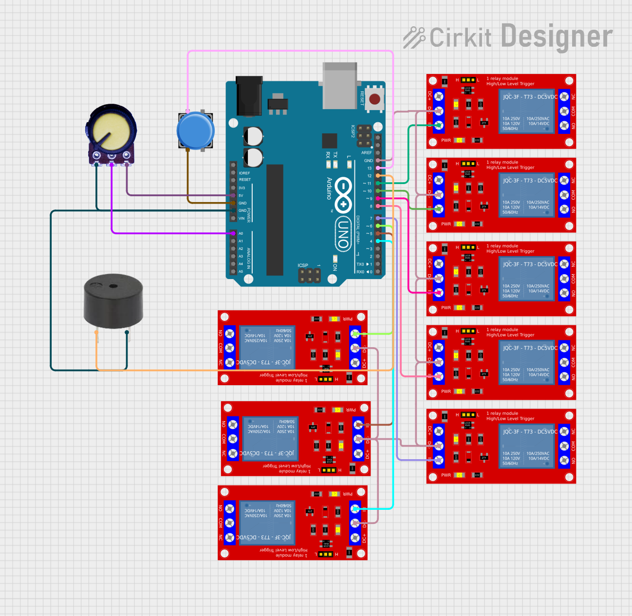
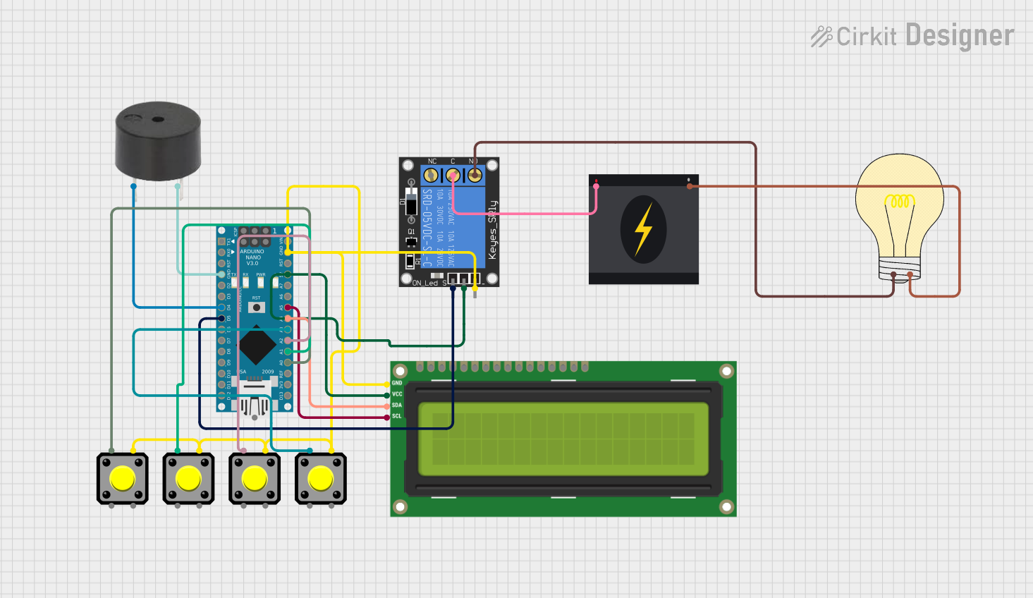
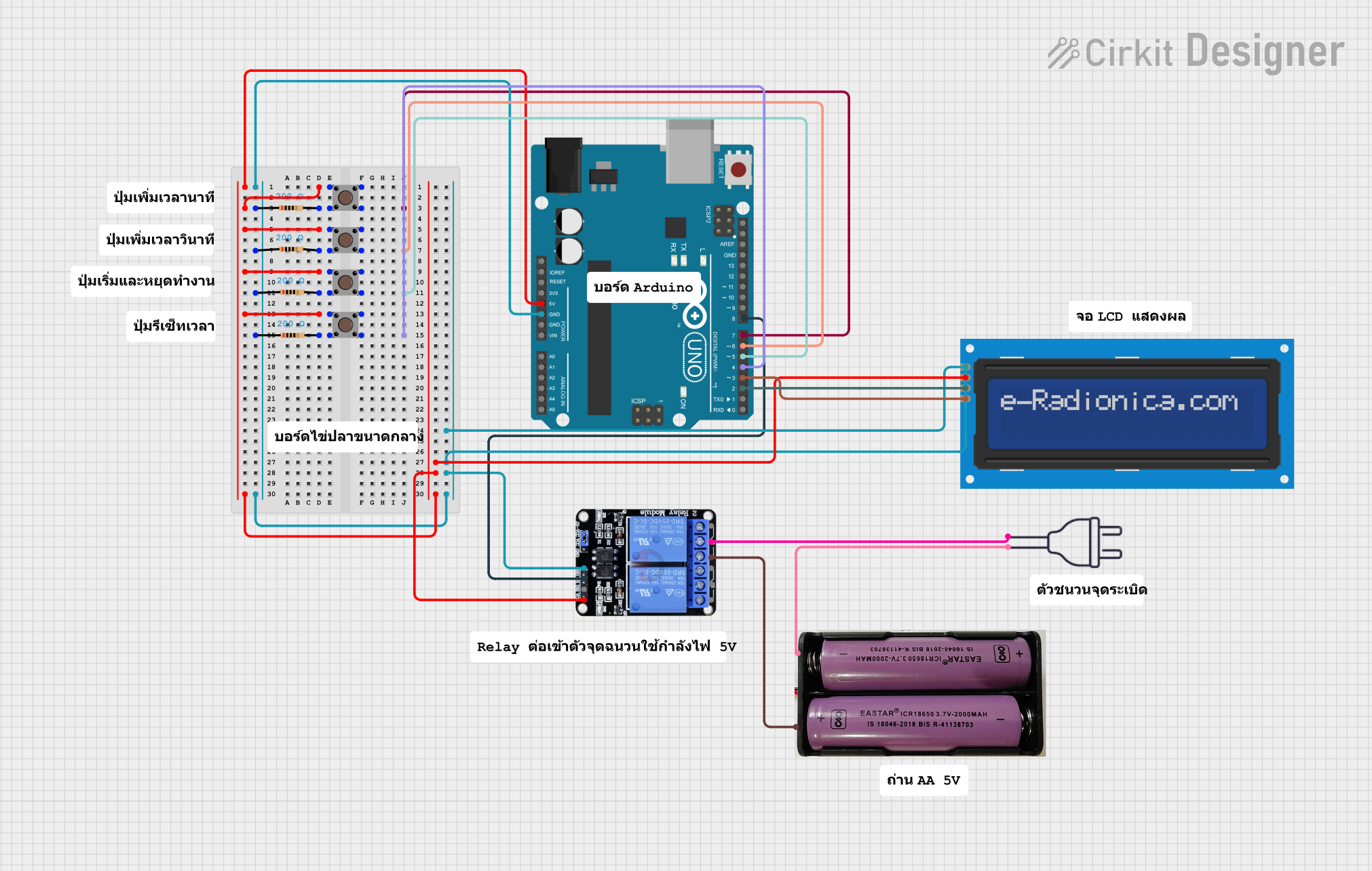
Explore Projects Built with Delay Relay Shield NE555 Timer Switch Module 0-150 Second Adjustable DC 5-12V
Common Applications
- Automatic lighting systems
- Motor start/stop delay
- DIY electronics projects
- Timed control of appliances
- Security systems with delay triggers
Technical Specifications
Key Technical Details
| Parameter | Specification |
|---|---|
| Operating Voltage | DC 5V to 12V |
| Adjustable Delay Range | 0 to 150 seconds |
| Relay Output Type | Normally Open (NO) and Normally Closed (NC) |
| Maximum Load Current | 10A (at 250V AC or 30V DC) |
| Timer IC | NE555 |
| Module Dimensions | Approx. 50mm x 26mm x 18mm |
Pin Configuration and Descriptions
| Pin/Terminal Name | Description |
|---|---|
| VCC | Positive power supply input (5V to 12V DC). |
| GND | Ground connection for the power supply. |
| IN | Trigger input pin for starting the delay timer. |
| NO (Normally Open) | Relay output terminal that remains open until the delay is triggered. |
| NC (Normally Closed) | Relay output terminal that remains closed until the delay is triggered. |
| COM | Common terminal for the relay output. |
Usage Instructions
How to Use the Component in a Circuit
- Power the Module: Connect the VCC pin to a DC power supply (5V to 12V) and the GND pin to ground.
- Set the Delay Time: Use the onboard potentiometer to adjust the delay time. Turning the potentiometer clockwise increases the delay, while turning it counterclockwise decreases it.
- Connect the Load:
- For devices that should activate after the delay, connect them between the NO (Normally Open) and COM terminals.
- For devices that should deactivate after the delay, connect them between the NC (Normally Closed) and COM terminals.
- Trigger the Timer: Apply a signal to the IN pin to start the delay timer. The relay will activate after the set delay time.
Important Considerations and Best Practices
- Ensure the power supply voltage is within the specified range (5V to 12V DC) to avoid damaging the module.
- Do not exceed the relay's maximum load current (10A at 250V AC or 30V DC).
- Use proper insulation and safety precautions when working with high-voltage loads.
- For precise timing, calibrate the potentiometer carefully and test the delay duration.
Example: Using with Arduino UNO
The Delay Relay Shield can be triggered using an Arduino UNO. Below is an example code to trigger the module:
// Example code to trigger the Delay Relay Shield NE555 Timer Module
// Connect the IN pin of the module to Arduino pin 7

#define RELAY_TRIGGER_PIN 7  // Define the Arduino pin connected to the IN pin

void setup() {
  pinMode(RELAY_TRIGGER_PIN, OUTPUT);  // Set the pin as an output
  digitalWrite(RELAY_TRIGGER_PIN, LOW);  // Ensure the pin starts LOW
}

void loop() {
  digitalWrite(RELAY_TRIGGER_PIN, HIGH);  // Send a HIGH signal to trigger the relay
  delay(1000);  // Keep the signal HIGH for 1 second
  digitalWrite(RELAY_TRIGGER_PIN, LOW);  // Set the pin LOW to reset the module
  delay(5000);  // Wait for 5 seconds before triggering again
}
Troubleshooting and FAQs
Common Issues and Solutions
The relay does not activate:
- Ensure the power supply voltage is within the 5V to 12V range.
- Verify that the IN pin is receiving a proper trigger signal.
- Check the load connections to the relay terminals.
The delay time is incorrect:
- Adjust the potentiometer carefully to set the desired delay.
- Ensure the module is not exposed to electrical noise, which can affect timing accuracy.
The module overheats:
- Ensure the load current does not exceed the relay's maximum rating (10A).
- Use a heatsink or cooling mechanism if the module operates continuously under high loads.
FAQs
Q: Can I use this module with a 3.3V microcontroller?
A: The module requires a minimum of 5V for operation. You can use a level shifter or transistor circuit to interface a 3.3V microcontroller with the module.
Q: How do I reset the timer during operation?
A: To reset the timer, remove the trigger signal from the IN pin and reapply it.
Q: Can I use this module for AC loads?
A: Yes, the relay supports AC loads up to 250V, but ensure proper insulation and safety precautions when working with high voltages.