Cirkit Designer Logo
Cirkit Designer
Your all-in-one circuit design IDE
Home / 
Component Documentation

How to Use MAX30100: Examples, Pinouts, and Specs

Image of MAX30100
Cirkit Designer LogoDesign with MAX30100 in Cirkit Designer

Introduction

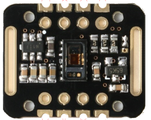
The MAX30100, manufactured by Maxim Integrated, is a low-power, integrated pulse oximeter and heart-rate monitor sensor. It utilizes photoplethysmography (PPG) technology to measure blood oxygen saturation (SpO2) and heart rate by emitting light through the skin and detecting the amount of light absorbed by the blood. This compact sensor is ideal for wearable devices and health monitoring systems.

Explore Projects Built with MAX30100

Use Cirkit Designer to design, explore, and prototype these projects online. Some projects support real-time simulation. Click "Open Project" to start designing instantly!
ESP32 and MAX30100 Pulse Oximeter
Image of t: A project utilizing MAX30100 in a practical application
This circuit features an ESP32 microcontroller connected to a MAX30100 sensor, which is likely used for measuring pulse oximetry. The ESP32 is interfaced with the MAX30100 via I2C communication, as indicated by the SDA and SCL connections. Power is supplied to both the ESP32 and the MAX30100 by a 5V battery, with common ground established across the components.
Cirkit Designer LogoOpen Project in Cirkit Designer
ESP32-Based Multi-Sensor Health Monitoring System with Bluetooth Connectivity
Image of circuit diagram: A project utilizing MAX30100 in a practical application
This circuit features an ESP32-WROOM-32UE microcontroller as the central processing unit, interfacing with a variety of sensors and modules. It includes a MAX30100 pulse oximeter and heart-rate sensor, an MLX90614 infrared thermometer, an HC-05 Bluetooth module for wireless communication, and a Neo 6M GPS module for location tracking. All components are powered by a common voltage supply and are connected to specific GPIO pins on the ESP32 for data exchange, with the sensors using I2C communication and the modules using UART.
Cirkit Designer LogoOpen Project in Cirkit Designer
ESP32-Based Health Monitoring System with Bluetooth and GPS
Image of circuit diagram: A project utilizing MAX30100 in a practical application
This circuit integrates an ESP32 microcontroller with various sensors and modules, including a MAX30100 pulse oximeter, an MLX90614 infrared thermometer, a Neo 6M GPS module, and an HC-05 Bluetooth module. The ESP32 collects data from these sensors and modules via I2C and UART interfaces, enabling wireless communication and GPS tracking capabilities.
Cirkit Designer LogoOpen Project in Cirkit Designer
Wi-Fi Enabled Health Monitoring System with MAX30100 and MLX90614
Image of NEW project: A project utilizing MAX30100 in a practical application
This circuit integrates a MAX30100 pulse oximeter and heart-rate sensor, and an MLX90614 infrared temperature sensor with an ESP8266 NodeMCU microcontroller. The sensors communicate with the microcontroller via I2C protocol, and the NodeMCU provides power and handles data processing and transmission.
Cirkit Designer LogoOpen Project in Cirkit Designer

Explore Projects Built with MAX30100

Use Cirkit Designer to design, explore, and prototype these projects online. Some projects support real-time simulation. Click "Open Project" to start designing instantly!
Image of t: A project utilizing MAX30100 in a practical application
ESP32 and MAX30100 Pulse Oximeter
This circuit features an ESP32 microcontroller connected to a MAX30100 sensor, which is likely used for measuring pulse oximetry. The ESP32 is interfaced with the MAX30100 via I2C communication, as indicated by the SDA and SCL connections. Power is supplied to both the ESP32 and the MAX30100 by a 5V battery, with common ground established across the components.
Cirkit Designer LogoOpen Project in Cirkit Designer
Image of circuit diagram: A project utilizing MAX30100 in a practical application
ESP32-Based Multi-Sensor Health Monitoring System with Bluetooth Connectivity
This circuit features an ESP32-WROOM-32UE microcontroller as the central processing unit, interfacing with a variety of sensors and modules. It includes a MAX30100 pulse oximeter and heart-rate sensor, an MLX90614 infrared thermometer, an HC-05 Bluetooth module for wireless communication, and a Neo 6M GPS module for location tracking. All components are powered by a common voltage supply and are connected to specific GPIO pins on the ESP32 for data exchange, with the sensors using I2C communication and the modules using UART.
Cirkit Designer LogoOpen Project in Cirkit Designer
Image of circuit diagram: A project utilizing MAX30100 in a practical application
ESP32-Based Health Monitoring System with Bluetooth and GPS
This circuit integrates an ESP32 microcontroller with various sensors and modules, including a MAX30100 pulse oximeter, an MLX90614 infrared thermometer, a Neo 6M GPS module, and an HC-05 Bluetooth module. The ESP32 collects data from these sensors and modules via I2C and UART interfaces, enabling wireless communication and GPS tracking capabilities.
Cirkit Designer LogoOpen Project in Cirkit Designer
Image of NEW project: A project utilizing MAX30100 in a practical application
Wi-Fi Enabled Health Monitoring System with MAX30100 and MLX90614
This circuit integrates a MAX30100 pulse oximeter and heart-rate sensor, and an MLX90614 infrared temperature sensor with an ESP8266 NodeMCU microcontroller. The sensors communicate with the microcontroller via I2C protocol, and the NodeMCU provides power and handles data processing and transmission.
Cirkit Designer LogoOpen Project in Cirkit Designer

Common Applications

  • Wearable fitness trackers
  • Medical devices for SpO2 and heart rate monitoring
  • Health and wellness applications
  • IoT-based health monitoring systems
  • Research and development in biomedical engineering

Technical Specifications

Key Technical Details

Parameter Value
Operating Voltage 1.8V (core) and 3.3V (I/O)
Operating Current 0.7mA (typical)
Standby Current 0.7µA
Measurement Method Photoplethysmography (PPG)
SpO2 Measurement Range 0% to 100%
Heart Rate Measurement Range 30 bpm to 240 bpm
Communication Interface I2C
Operating Temperature Range -40°C to +85°C
Package Type 14-pin optical module

Pin Configuration and Descriptions

Pin Number Pin Name Description
1 SDA I2C Data Line
2 SCL I2C Clock Line
3 INT Interrupt Output (active low)
4 GND Ground
5 VIN Power Supply Input (1.8V to 3.3V)
6 IR_DRV Infrared LED Driver Output
7 RED_DRV Red LED Driver Output
8-14 NC Not Connected

Usage Instructions

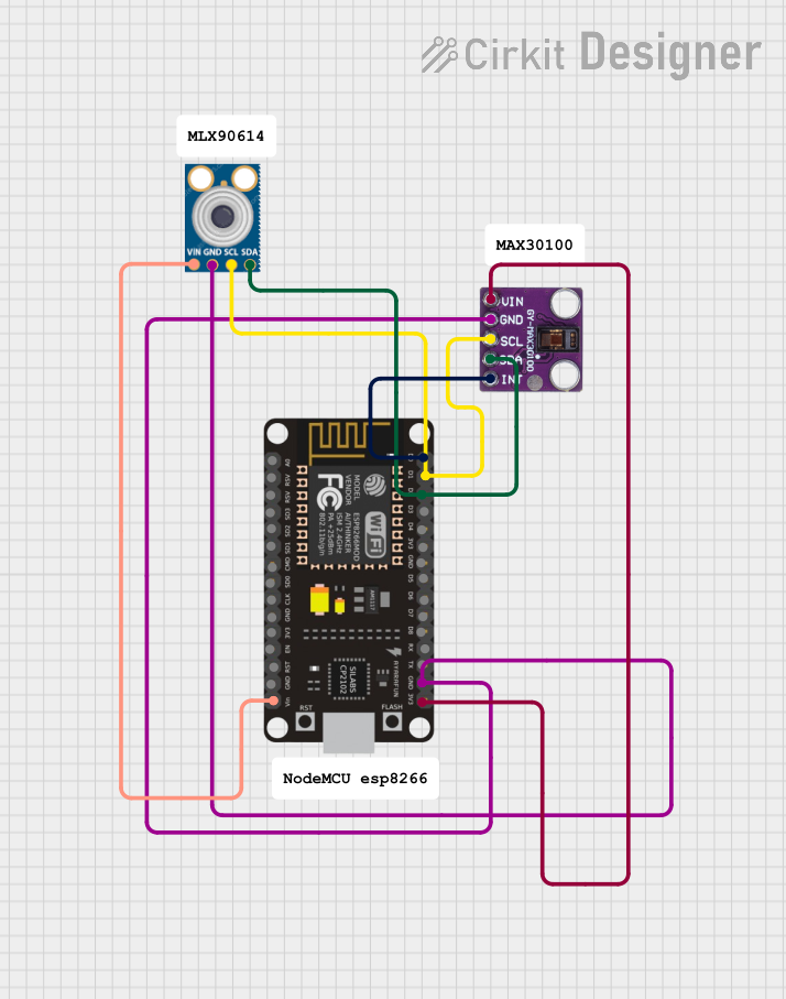
How to Use the MAX30100 in a Circuit

  1. Power Supply: Connect the VIN pin to a 3.3V power source and GND to ground.
  2. I2C Communication: Connect the SDA and SCL pins to the corresponding I2C pins of your microcontroller (e.g., Arduino UNO).
  3. Interrupt Pin: Optionally, connect the INT pin to a GPIO pin on your microcontroller to handle interrupts.
  4. LED Drivers: The IR_DRV and RED_DRV pins are used to drive the infrared and red LEDs for PPG measurements.
  5. Pull-Up Resistors: Use 4.7kΩ pull-up resistors on the SDA and SCL lines for proper I2C communication.

Important Considerations

  • Ensure the sensor is placed in contact with the skin for accurate readings.
  • Avoid ambient light interference by enclosing the sensor in a dark housing.
  • Use proper decoupling capacitors (e.g., 0.1µF) near the power supply pins to reduce noise.
  • The MAX30100 requires calibration for accurate SpO2 and heart rate measurements.

Example Code for Arduino UNO

Below is an example code snippet to interface the MAX30100 with an Arduino UNO using the I2C protocol:

#include <Wire.h>
#include "MAX30100.h" // Include the MAX30100 library

MAX30100 sensor; // Create an instance of the MAX30100 class

void setup() {
  Serial.begin(9600); // Initialize serial communication
  Wire.begin();       // Initialize I2C communication

  // Initialize the MAX30100 sensor
  if (sensor.begin() == false) {
    Serial.println("MAX30100 initialization failed!");
    while (1); // Halt execution if initialization fails
  }

  Serial.println("MAX30100 initialized successfully!");
}

void loop() {
  float heartRate, spo2;

  // Read heart rate and SpO2 values
  if (sensor.readSensor(&heartRate, &spo2)) {
    Serial.print("Heart Rate: ");
    Serial.print(heartRate);
    Serial.print(" bpm, SpO2: ");
    Serial.print(spo2);
    Serial.println(" %");
  } else {
    Serial.println("Failed to read data from MAX30100.");
  }

  delay(1000); // Wait for 1 second before the next reading
}

Note: Ensure you have installed the appropriate MAX30100 library for Arduino before running the code.


Troubleshooting and FAQs

Common Issues and Solutions

  1. No Data Output:

    • Ensure the sensor is powered correctly (3.3V on VIN and GND connected).
    • Verify the I2C connections (SDA and SCL) and check for proper pull-up resistors.
    • Confirm the I2C address of the MAX30100 (default: 0x57) matches the code.
  2. Inaccurate Readings:

    • Ensure the sensor is in direct contact with the skin.
    • Minimize ambient light interference by using a dark enclosure.
    • Check for proper calibration of the sensor.
  3. Initialization Fails:

    • Verify the MAX30100 library is installed and correctly included in the code.
    • Check the power supply voltage and ensure it is within the specified range.

FAQs

Q1: Can the MAX30100 measure SpO2 and heart rate simultaneously?
Yes, the MAX30100 is designed to measure both SpO2 and heart rate simultaneously using its dual LED system.

Q2: What is the maximum I2C clock speed supported by the MAX30100?
The MAX30100 supports I2C clock speeds up to 400kHz (Fast Mode).

Q3: Can the MAX30100 be used with a 5V microcontroller?
Yes, but you must use a level shifter to step down the I2C signals to 3.3V, as the MAX30100 operates at 3.3V logic levels.

Q4: How do I improve measurement accuracy?
Ensure proper placement of the sensor, minimize motion artifacts, and use a well-designed enclosure to block ambient light.


This documentation provides a comprehensive guide to understanding, using, and troubleshooting the MAX30100 sensor.