How to Use thermal camera: Examples, Pinouts, and Specs
Introduction
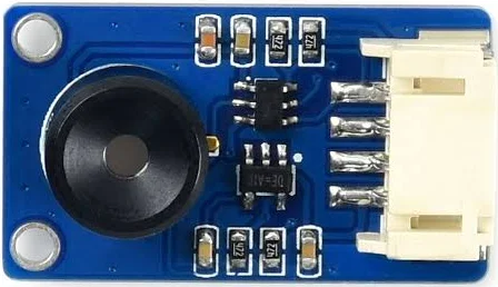
The Raspberry Thermal Camera is a compact and versatile device designed to detect infrared radiation and convert it into a visual image. This allows users to observe temperature variations in objects and environments, making it an essential tool for applications requiring non-contact temperature measurement. The camera is ideal for use in fields such as industrial diagnostics, building inspections, medical imaging, and robotics.
Explore Projects Built with thermal camera

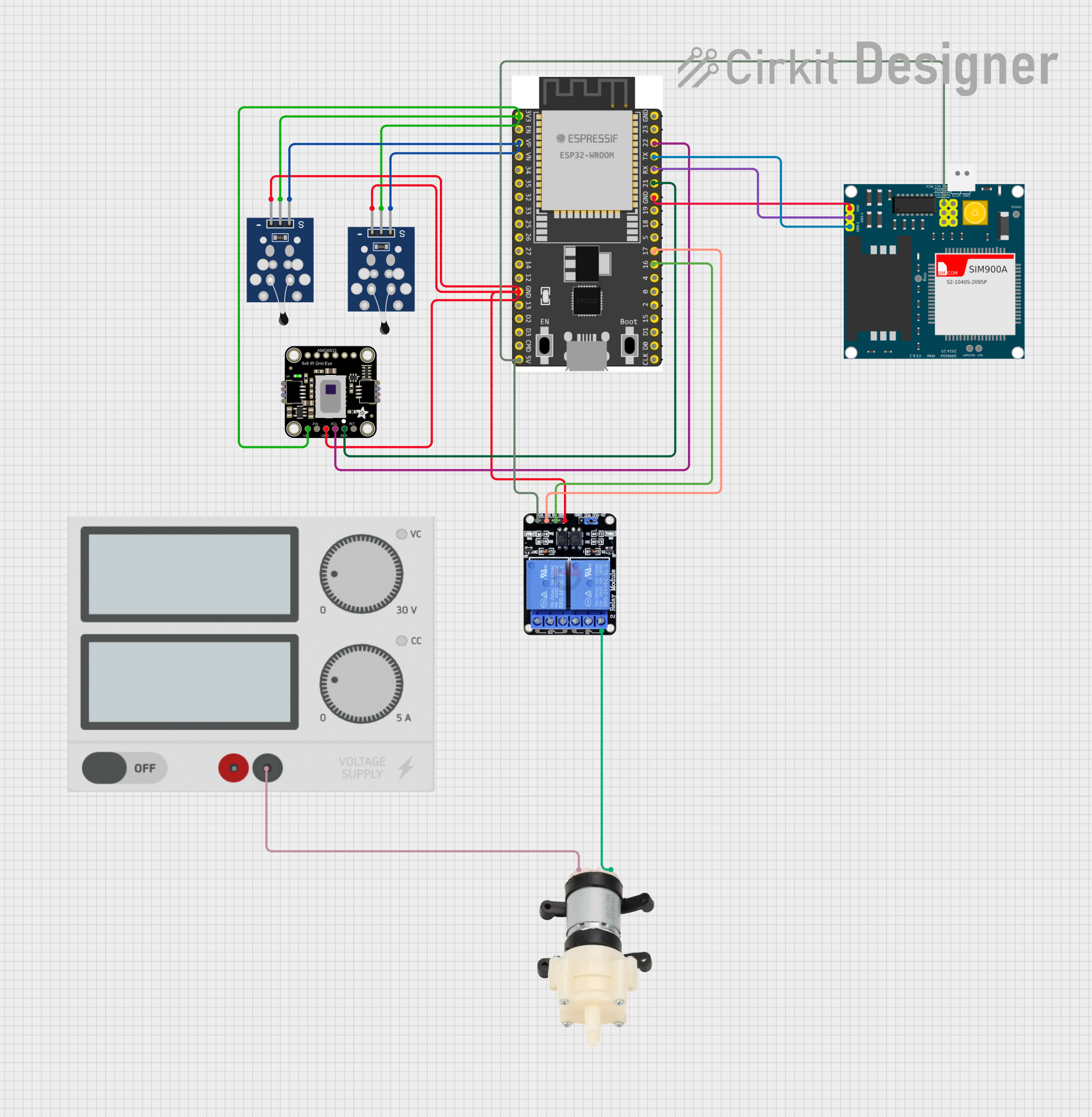
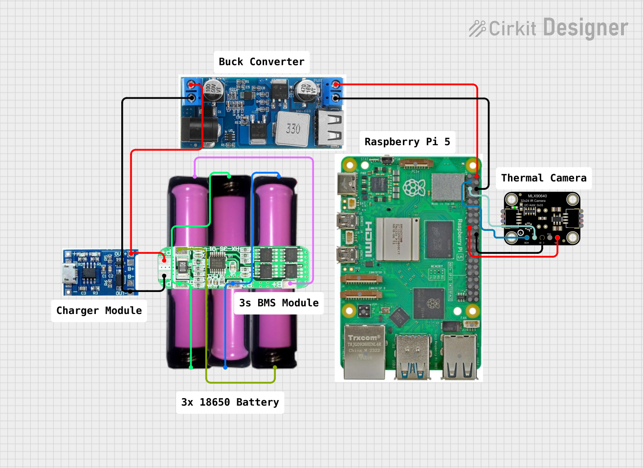
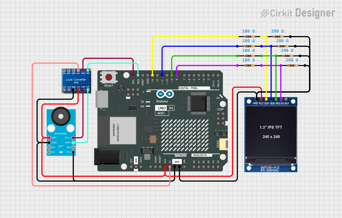
Explore Projects Built with thermal camera
Common Applications and Use Cases
- Industrial Diagnostics: Detecting overheating components or machinery.
- Building Inspections: Identifying insulation issues, air leaks, or moisture intrusion.
- Medical Imaging: Monitoring body temperature or detecting inflammation.
- Robotics: Enabling robots to "see" heat signatures for navigation or object detection.
- Home Automation: Monitoring room temperature or detecting human presence.
Technical Specifications
The Raspberry Thermal Camera is designed for seamless integration with Raspberry Pi boards and other microcontroller platforms. Below are its key technical details:
General Specifications
| Parameter | Value |
|---|---|
| Sensor Type | Infrared (IR) thermal sensor |
| Resolution | 32x24 pixels (or higher, depending on model) |
| Temperature Range | -40°C to 300°C |
| Field of View (FOV) | 55° x 35° |
| Frame Rate | 8.7 Hz |
| Interface | I2C or SPI |
| Operating Voltage | 3.3V |
| Power Consumption | < 150 mW |
Pin Configuration
The Raspberry Thermal Camera typically uses an I2C interface for communication. Below is the pin configuration:
| Pin Name | Description |
|---|---|
| VCC | Power supply (3.3V) |
| GND | Ground |
| SDA | I2C data line |
| SCL | I2C clock line |
| INT | Interrupt pin (optional, for alerts) |
Usage Instructions
Connecting the Thermal Camera to a Raspberry Pi
Wiring: Connect the thermal camera to the Raspberry Pi as follows:
- Connect the
VCCpin of the camera to the 3.3V pin on the Raspberry Pi. - Connect the
GNDpin of the camera to a ground pin on the Raspberry Pi. - Connect the
SDApin of the camera to the SDA pin on the Raspberry Pi (GPIO2). - Connect the
SCLpin of the camera to the SCL pin on the Raspberry Pi (GPIO3).
- Connect the
Enable I2C on the Raspberry Pi:
- Open the Raspberry Pi configuration tool by running
sudo raspi-config. - Navigate to
Interfacing Options>I2Cand enable it. - Reboot the Raspberry Pi to apply the changes.
- Open the Raspberry Pi configuration tool by running
Install Required Libraries:
- Install the Python
smbuslibrary for I2C communication:sudo apt-get install python3-smbus sudo apt-get install i2c-tools
- Install the Python
Test the Connection:
- Run the following command to detect the camera on the I2C bus:
i2cdetect -y 1 - The camera's I2C address should appear in the output (e.g.,
0x33).
- Run the following command to detect the camera on the I2C bus:
Sample Code for Reading Data
Below is an example Python script to read temperature data from the Raspberry Thermal Camera:
import smbus
import time
Initialize the I2C bus
bus = smbus.SMBus(1) # Use I2C bus 1 on Raspberry Pi
Define the camera's I2C address
CAMERA_I2C_ADDRESS = 0x33
Function to read temperature data
def read_thermal_data(): try: # Read 32x24 pixel data (768 bytes) data = bus.read_i2c_block_data(CAMERA_I2C_ADDRESS, 0x00, 768) # Convert data to temperature values (example conversion) temperatures = [d * 0.25 for d in data] return temperatures except Exception as e: print(f"Error reading data: {e}") return None
Main loop
while True: temperatures = read_thermal_data() if temperatures: print("Temperature data:", temperatures) time.sleep(1) # Delay for 1 second
Important Considerations
- Ensure the camera is connected securely to avoid communication errors.
- Avoid exposing the camera to direct sunlight or extreme temperatures, as this may damage the sensor.
- Use appropriate libraries and drivers for your specific Raspberry Thermal Camera model.
- If using the camera in a high-noise environment, consider adding pull-up resistors to the I2C lines.
Troubleshooting and FAQs
Common Issues
Camera Not Detected on I2C Bus:
- Ensure the I2C interface is enabled on the Raspberry Pi.
- Check the wiring for loose or incorrect connections.
- Verify the camera's I2C address using
i2cdetect.
Incorrect Temperature Readings:
- Ensure the camera is not exposed to reflective surfaces, which can distort readings.
- Calibrate the camera if necessary (refer to the manufacturer's instructions).
Script Fails to Run:
- Ensure all required Python libraries are installed.
- Check for typos or syntax errors in the code.
FAQs
Q: Can this camera detect human presence?
A: Yes, the camera can detect heat signatures from humans, making it suitable for presence detection.
Q: What is the maximum distance for accurate temperature measurement?
A: The effective range depends on the model, but typically it is accurate up to a few meters.
Q: Can I use this camera with an Arduino?
A: Yes, the camera can be used with an Arduino, but you may need to use an I2C library like Wire.h and ensure the Arduino operates at 3.3V logic levels.
Q: How do I visualize the thermal data?
A: You can use Python libraries like matplotlib to create heatmaps or images from the temperature data.
By following this documentation, you can effectively integrate and use the Raspberry Thermal Camera in your projects.