Cirkit Designer Logo
Cirkit Designer
Your all-in-one circuit design IDE
Home / 
Component Documentation

How to Use Keystudio Obstalcle avoidance IR: Examples, Pinouts, and Specs

Image of Keystudio Obstalcle avoidance IR
Cirkit Designer LogoDesign with Keystudio Obstalcle avoidance IR in Cirkit Designer

Introduction

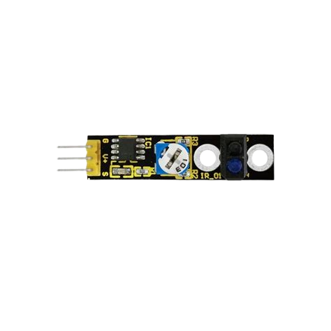
The Keystudio Obstacle Avoidance IR sensor module is a compact and efficient device designed to detect obstacles using infrared (IR) light. It emits IR light and measures the reflected signal to determine the presence of nearby objects. This module is widely used in robotics, automation, and other applications requiring object detection and navigation.

Explore Projects Built with Keystudio Obstalcle avoidance IR

Use Cirkit Designer to design, explore, and prototype these projects online. Some projects support real-time simulation. Click "Open Project" to start designing instantly!
MakerEdu Creator with Bluetooth, IR Sensors, LCD Display, and Push Button Interaction
Image of MKL Distance Measurement: A project utilizing Keystudio Obstalcle avoidance IR in a practical application
This circuit features a MakerEdu Creator microcontroller board interfaced with two MKE-S11 IR Infrared Obstacle Avoidance Sensors, a MKE-M02 Push Button Tact Switch, a MKE-M15 Bluetooth module, and a MKE-M08 LCD2004 I2C display module. The push button is connected to a digital input for user interaction, while the IR sensors are likely used for detecting obstacles. The Bluetooth module enables wireless communication, and the LCD display provides a user interface for displaying information or statuses.
Cirkit Designer LogoOpen Project in Cirkit Designer
Arduino UNO-Based IR Sensor and OLED Display System with Servo Control
Image of Smart Parking System with Automatic Gate Control and OLED Display: A project utilizing Keystudio Obstalcle avoidance IR in a practical application
This circuit uses an Arduino UNO to interface with two IR sensors, a 0.96" OLED display, and a Tower Pro SG90 servo motor. The IR sensors detect obstacles and send signals to the Arduino, which processes the data and can display information on the OLED screen or control the servo motor based on the sensor inputs.
Cirkit Designer LogoOpen Project in Cirkit Designer
Battery-Powered Line Following Robot with IR Sensors and Cytron URC10 Motor Controller
Image of URC10 SUMO AUTO: A project utilizing Keystudio Obstalcle avoidance IR in a practical application
This circuit is a robotic control system that uses multiple IR sensors for line detection and obstacle avoidance, powered by a 3S LiPo battery. The Cytron URC10 motor driver, controlled by a microcontroller, drives two GM25 DC motors based on input from the sensors and a rocker switch, with a 7-segment panel voltmeter displaying the battery voltage.
Cirkit Designer LogoOpen Project in Cirkit Designer
Arduino Nano Line Follower Robot with Obstacle Avoidance and PID Control
Image of LFR GPT: A project utilizing Keystudio Obstalcle avoidance IR in a practical application
This circuit is a line-following robot with obstacle avoidance capabilities. It uses an Arduino Nano to process inputs from an 8-array IR sensor for line detection and an HC-SR04 ultrasonic sensor for obstacle detection. The robot is controlled via a motor driver (ponte h) and includes buttons for calibration and operation, with LEDs indicating the status.
Cirkit Designer LogoOpen Project in Cirkit Designer

Explore Projects Built with Keystudio Obstalcle avoidance IR

Use Cirkit Designer to design, explore, and prototype these projects online. Some projects support real-time simulation. Click "Open Project" to start designing instantly!
Image of MKL Distance Measurement: A project utilizing Keystudio Obstalcle avoidance IR in a practical application
MakerEdu Creator with Bluetooth, IR Sensors, LCD Display, and Push Button Interaction
This circuit features a MakerEdu Creator microcontroller board interfaced with two MKE-S11 IR Infrared Obstacle Avoidance Sensors, a MKE-M02 Push Button Tact Switch, a MKE-M15 Bluetooth module, and a MKE-M08 LCD2004 I2C display module. The push button is connected to a digital input for user interaction, while the IR sensors are likely used for detecting obstacles. The Bluetooth module enables wireless communication, and the LCD display provides a user interface for displaying information or statuses.
Cirkit Designer LogoOpen Project in Cirkit Designer
Image of Smart Parking System with Automatic Gate Control and OLED Display: A project utilizing Keystudio Obstalcle avoidance IR in a practical application
Arduino UNO-Based IR Sensor and OLED Display System with Servo Control
This circuit uses an Arduino UNO to interface with two IR sensors, a 0.96" OLED display, and a Tower Pro SG90 servo motor. The IR sensors detect obstacles and send signals to the Arduino, which processes the data and can display information on the OLED screen or control the servo motor based on the sensor inputs.
Cirkit Designer LogoOpen Project in Cirkit Designer
Image of URC10 SUMO AUTO: A project utilizing Keystudio Obstalcle avoidance IR in a practical application
Battery-Powered Line Following Robot with IR Sensors and Cytron URC10 Motor Controller
This circuit is a robotic control system that uses multiple IR sensors for line detection and obstacle avoidance, powered by a 3S LiPo battery. The Cytron URC10 motor driver, controlled by a microcontroller, drives two GM25 DC motors based on input from the sensors and a rocker switch, with a 7-segment panel voltmeter displaying the battery voltage.
Cirkit Designer LogoOpen Project in Cirkit Designer
Image of LFR GPT: A project utilizing Keystudio Obstalcle avoidance IR in a practical application
Arduino Nano Line Follower Robot with Obstacle Avoidance and PID Control
This circuit is a line-following robot with obstacle avoidance capabilities. It uses an Arduino Nano to process inputs from an 8-array IR sensor for line detection and an HC-SR04 ultrasonic sensor for obstacle detection. The robot is controlled via a motor driver (ponte h) and includes buttons for calibration and operation, with LEDs indicating the status.
Cirkit Designer LogoOpen Project in Cirkit Designer

Common Applications and Use Cases

  • Autonomous robots for obstacle detection and avoidance
  • Line-following robots with obstacle detection capabilities
  • Smart cars and robotic vehicles
  • Proximity detection in automation systems
  • Interactive toys and gadgets

Technical Specifications

The following table outlines the key technical details of the Keystudio Obstacle Avoidance IR sensor module:

Parameter Value
Operating Voltage 3.3V to 5V
Operating Current ≤ 20mA
Detection Range 2cm to 30cm (adjustable)
Detection Angle ≤ 35°
Output Type Digital (High/Low)
Dimensions 3.1cm x 1.5cm x 0.7cm
Weight ~3g

Pin Configuration and Descriptions

The Keystudio Obstacle Avoidance IR sensor module has a 3-pin interface. The pin configuration is as follows:

Pin Name Description
1 VCC Power supply pin. Connect to 3.3V or 5V.
2 GND Ground pin. Connect to the ground of the circuit.
3 OUT Digital output pin. Outputs HIGH (1) when no obstacle is detected, and LOW (0) when an obstacle is detected.

Usage Instructions

How to Use the Component in a Circuit

  1. Power the Module: Connect the VCC pin to a 3.3V or 5V power source and the GND pin to the ground of your circuit.
  2. Connect the Output: Connect the OUT pin to a digital input pin of your microcontroller (e.g., Arduino UNO).
  3. Adjust the Sensitivity: Use the onboard potentiometer to adjust the detection range. Turn clockwise to increase the range and counterclockwise to decrease it.
  4. Test the Module: Place an object within the detection range and observe the output signal. The onboard LED will light up when an obstacle is detected.

Important Considerations and Best Practices

  • Avoid Direct Sunlight: The sensor may not function properly in environments with strong IR interference, such as direct sunlight.
  • Mounting Position: Ensure the sensor is mounted at an appropriate angle for optimal obstacle detection.
  • Power Supply: Use a stable power source to avoid erratic behavior.
  • Distance Adjustment: Fine-tune the potentiometer to match the desired detection range for your application.

Example Code for Arduino UNO

Below is an example code snippet to use the Keystudio Obstacle Avoidance IR sensor with an Arduino UNO:

// Define the pin connected to the sensor's OUT pin
const int sensorPin = 2; // Digital pin 2
const int ledPin = 13;   // Built-in LED on Arduino UNO

void setup() {
  pinMode(sensorPin, INPUT); // Set sensor pin as input
  pinMode(ledPin, OUTPUT);   // Set LED pin as output
  Serial.begin(9600);        // Initialize serial communication
}

void loop() {
  int sensorValue = digitalRead(sensorPin); // Read the sensor output
  
  if (sensorValue == LOW) {
    // Obstacle detected
    digitalWrite(ledPin, HIGH); // Turn on the LED
    Serial.println("Obstacle detected!");
  } else {
    // No obstacle
    digitalWrite(ledPin, LOW);  // Turn off the LED
    Serial.println("No obstacle.");
  }
  
  delay(100); // Small delay for stability
}

Troubleshooting and FAQs

Common Issues and Solutions

  1. The sensor is not detecting obstacles:

    • Ensure the VCC and GND pins are connected properly.
    • Check the potentiometer adjustment and increase the detection range if necessary.
    • Verify that the object is within the sensor's detection angle and range.
  2. False detections or erratic behavior:

    • Avoid using the sensor in environments with strong IR interference (e.g., direct sunlight or near other IR sources).
    • Ensure a stable power supply to the module.
  3. The onboard LED does not light up:

    • Check the connections and ensure the module is powered correctly.
    • Verify that the object is within the detection range.

FAQs

Q: Can this sensor detect transparent objects?
A: No, the sensor may not reliably detect transparent or highly reflective objects due to the way IR light is reflected.

Q: Can I use this sensor with a 3.3V microcontroller?
A: Yes, the sensor operates within a voltage range of 3.3V to 5V, making it compatible with 3.3V microcontrollers.

Q: How do I increase the detection range?
A: Use the onboard potentiometer to adjust the detection range. Turn it clockwise to increase the range.

Q: Can I use multiple sensors in the same project?
A: Yes, you can use multiple sensors, but ensure they are positioned to avoid interference between their IR signals.

This concludes the documentation for the Keystudio Obstacle Avoidance IR sensor module.