Cirkit Designer Logo
Cirkit Designer
Your all-in-one circuit design IDE
Home / 
Component Documentation

How to Use C2-20 v2.4 1801: Examples, Pinouts, and Specs

Image of C2-20 v2.4 1801
Cirkit Designer LogoDesign with C2-20 v2.4 1801 in Cirkit Designer

Introduction

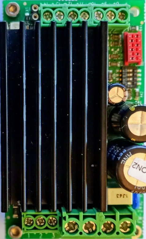
The C2-20 v2.4 1801 is a specialized electronic component designed for advanced circuit applications. Manufactured by Concens, this component offers enhanced performance characteristics and compatibility with a wide range of electronic systems. It is particularly suited for applications requiring precision, reliability, and efficient operation.

Explore Projects Built with C2-20 v2.4 1801

Use Cirkit Designer to design, explore, and prototype these projects online. Some projects support real-time simulation. Click "Open Project" to start designing instantly!
ESP32 and ESP8266 Wi-Fi Controlled Sensor Hub with Battery Backup
Image of baby guard: A project utilizing C2-20 v2.4 1801 in a practical application
This circuit is a sensor monitoring and data transmission system powered by a Li-ion battery and a 12V adapter. It includes various sensors (tilt, optical encoder, force sensing resistors, and air pressure) connected to an ESP32 microcontroller, which reads sensor data and transmits it via a WiFi module (ESP8266-01). The system is designed to provide real-time sensor data over a WiFi network.
Cirkit Designer LogoOpen Project in Cirkit Designer
Satellite Compass and Network-Integrated GPS Data Processing System
Image of GPS 시스템 측정 구성도_241016: A project utilizing C2-20 v2.4 1801 in a practical application
This circuit comprises a satellite compass, a mini PC, two GPS antennas, power supplies, a network switch, media converters, and an atomic rubidium clock. The satellite compass is powered by a triple output DC power supply and interfaces with an RS232 splitter for 1PPS signals. The mini PCs are connected to the USRP B200 devices via USB for data and power, and to media converters via Ethernet, which in turn connect to a network switch using fiber optic links. The antennas are connected to the USRP B200s through RF directional couplers, and the atomic clock provides a 1PPS input to the RS232 splitter.
Cirkit Designer LogoOpen Project in Cirkit Designer
Satellite-Based Timing and Navigation System with SDR and Atomic Clock Synchronization
Image of GPS 시스템 측정 구성도_Confirm: A project utilizing C2-20 v2.4 1801 in a practical application
This circuit appears to be a complex system involving power supply management, GPS and timing synchronization, and data communication. It includes a SI-TEX G1 Satellite Compass for GPS data, an XHTF1021 Atomic Rubidium Clock for precise timing, and Ettus USRP B200 units for software-defined radio communication. Power is supplied through various SMPS units and distributed via terminal blocks and DC jacks. Data communication is facilitated by Beelink MINI S12 N95 computers, RS232 splitters, and a 1000BASE-T Media Converter for network connectivity. RF Directional Couplers are used to interface antennas with the USRP units, and the entire system is likely contained within cases for protection and organization.
Cirkit Designer LogoOpen Project in Cirkit Designer
Modular Power Distribution System with Multiple SMPS Units and 120V Outlet
Image of Cellion-Tesla: A project utilizing C2-20 v2.4 1801 in a practical application
This circuit is designed to convert 240V AC power to both 12V and 24V DC outputs using multiple SMPS units. Terminal blocks are used to organize and distribute the power, while a 120V outlet provides additional AC power access. The circuit is likely used for powering various electronic devices that require different voltage levels.
Cirkit Designer LogoOpen Project in Cirkit Designer

Explore Projects Built with C2-20 v2.4 1801

Use Cirkit Designer to design, explore, and prototype these projects online. Some projects support real-time simulation. Click "Open Project" to start designing instantly!
Image of baby guard: A project utilizing C2-20 v2.4 1801 in a practical application
ESP32 and ESP8266 Wi-Fi Controlled Sensor Hub with Battery Backup
This circuit is a sensor monitoring and data transmission system powered by a Li-ion battery and a 12V adapter. It includes various sensors (tilt, optical encoder, force sensing resistors, and air pressure) connected to an ESP32 microcontroller, which reads sensor data and transmits it via a WiFi module (ESP8266-01). The system is designed to provide real-time sensor data over a WiFi network.
Cirkit Designer LogoOpen Project in Cirkit Designer
Image of GPS 시스템 측정 구성도_241016: A project utilizing C2-20 v2.4 1801 in a practical application
Satellite Compass and Network-Integrated GPS Data Processing System
This circuit comprises a satellite compass, a mini PC, two GPS antennas, power supplies, a network switch, media converters, and an atomic rubidium clock. The satellite compass is powered by a triple output DC power supply and interfaces with an RS232 splitter for 1PPS signals. The mini PCs are connected to the USRP B200 devices via USB for data and power, and to media converters via Ethernet, which in turn connect to a network switch using fiber optic links. The antennas are connected to the USRP B200s through RF directional couplers, and the atomic clock provides a 1PPS input to the RS232 splitter.
Cirkit Designer LogoOpen Project in Cirkit Designer
Image of GPS 시스템 측정 구성도_Confirm: A project utilizing C2-20 v2.4 1801 in a practical application
Satellite-Based Timing and Navigation System with SDR and Atomic Clock Synchronization
This circuit appears to be a complex system involving power supply management, GPS and timing synchronization, and data communication. It includes a SI-TEX G1 Satellite Compass for GPS data, an XHTF1021 Atomic Rubidium Clock for precise timing, and Ettus USRP B200 units for software-defined radio communication. Power is supplied through various SMPS units and distributed via terminal blocks and DC jacks. Data communication is facilitated by Beelink MINI S12 N95 computers, RS232 splitters, and a 1000BASE-T Media Converter for network connectivity. RF Directional Couplers are used to interface antennas with the USRP units, and the entire system is likely contained within cases for protection and organization.
Cirkit Designer LogoOpen Project in Cirkit Designer
Image of Cellion-Tesla: A project utilizing C2-20 v2.4 1801 in a practical application
Modular Power Distribution System with Multiple SMPS Units and 120V Outlet
This circuit is designed to convert 240V AC power to both 12V and 24V DC outputs using multiple SMPS units. Terminal blocks are used to organize and distribute the power, while a 120V outlet provides additional AC power access. The circuit is likely used for powering various electronic devices that require different voltage levels.
Cirkit Designer LogoOpen Project in Cirkit Designer

Common Applications and Use Cases

  • Industrial automation systems
  • Robotics and motion control
  • Advanced power management circuits
  • Embedded systems requiring high-performance components
  • Custom electronic designs for research and development

Technical Specifications

Below are the key technical details and pin configuration for the C2-20 v2.4 1801:

Key Technical Details

Parameter Specification
Manufacturer Concens
Part ID EM-241B-CON2 prog.v.2.4
Operating Voltage Range 3.3V to 5V
Maximum Current Rating 500mA
Power Consumption < 2W
Operating Temperature -20°C to +85°C
Communication Protocol UART (Universal Asynchronous Receiver-Transmitter)
Dimensions 20mm x 15mm x 5mm
Weight 5 grams

Pin Configuration and Descriptions

The C2-20 v2.4 1801 has a total of 6 pins. The table below describes each pin:

Pin Number Pin Name Description
1 VCC Power supply input (3.3V to 5V)
2 GND Ground connection
3 TX UART Transmit pin (data output)
4 RX UART Receive pin (data input)
5 EN Enable pin (active HIGH to enable the component)
6 NC Not connected (reserved for future use)

Usage Instructions

How to Use the Component in a Circuit

  1. Power Supply: Connect the VCC pin to a stable power source within the range of 3.3V to 5V. Connect the GND pin to the ground of your circuit.
  2. UART Communication:
    • Connect the TX pin to the RX pin of your microcontroller or UART interface.
    • Connect the RX pin to the TX pin of your microcontroller or UART interface.
  3. Enable the Component: Ensure the EN pin is set HIGH to activate the component. If left LOW, the component will remain disabled.
  4. Unused Pins: Leave the NC pin unconnected as it is reserved for future use.

Important Considerations and Best Practices

  • Voltage Levels: Ensure the power supply voltage does not exceed 5V to avoid damaging the component.
  • Signal Integrity: Use short and properly shielded wires for UART connections to minimize noise and signal degradation.
  • Heat Management: Although the component has low power consumption, ensure adequate ventilation in high-temperature environments.
  • Enable Pin: Use a pull-down resistor on the EN pin to prevent accidental activation during power-up.

Example: Connecting to an Arduino UNO

The C2-20 v2.4 1801 can be easily interfaced with an Arduino UNO using its UART pins. Below is an example circuit and code:

Circuit Connections

C2-20 Pin Arduino UNO Pin
VCC 5V
GND GND
TX Pin 10 (RX)
RX Pin 11 (TX)
EN Pin 8

Arduino Code

// Example code to interface C2-20 v2.4 1801 with Arduino UNO
// This code demonstrates basic UART communication

#include <SoftwareSerial.h>

// Define software serial pins for communication
SoftwareSerial mySerial(10, 11); // RX, TX

// Define the enable pin
const int enablePin = 8;

void setup() {
  // Initialize serial communication
  Serial.begin(9600); // For debugging
  mySerial.begin(9600); // For communication with C2-20

  // Set up the enable pin
  pinMode(enablePin, OUTPUT);
  digitalWrite(enablePin, HIGH); // Enable the component

  Serial.println("C2-20 v2.4 1801 Initialized");
}

void loop() {
  // Send data to the C2-20
  mySerial.println("Hello, C2-20!");

  // Check for incoming data from the C2-20
  if (mySerial.available()) {
    String data = mySerial.readString();
    Serial.print("Received from C2-20: ");
    Serial.println(data);
  }

  delay(1000); // Wait for 1 second
}

Troubleshooting and FAQs

Common Issues and Solutions

  1. Component Not Responding

    • Cause: The EN pin is not set HIGH.
    • Solution: Ensure the EN pin is connected to a HIGH signal.
  2. No Data Transmission

    • Cause: Incorrect UART connections.
    • Solution: Verify that the TX and RX pins are correctly connected to the corresponding pins on the microcontroller.
  3. Overheating

    • Cause: Excessive current draw or high ambient temperature.
    • Solution: Check the power supply and ensure the component is operating within its specified temperature range.
  4. Noise in UART Communication

    • Cause: Long or unshielded wires.
    • Solution: Use shorter wires and consider adding shielding to reduce noise.

FAQs

Q1: Can the C2-20 v2.4 1801 operate at 3.3V?
A1: Yes, the component is designed to operate within a voltage range of 3.3V to 5V.

Q2: Is the NC pin required for operation?
A2: No, the NC pin is not connected internally and can be left unconnected.

Q3: What is the maximum UART baud rate supported?
A3: The component supports baud rates up to 115200 bps.

Q4: Can I use the C2-20 v2.4 1801 in outdoor environments?
A4: Yes, as long as the operating temperature remains within the range of -20°C to +85°C.