How to Use 24/12v to 5v stepdown: Examples, Pinouts, and Specs
Introduction
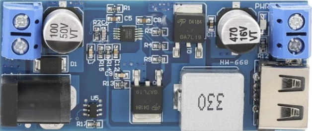
The 24/12V to 5V stepdown is a voltage regulator designed to convert higher input voltages, such as 24V or 12V, down to a stable 5V output. This component is widely used in applications where low-voltage devices, such as microcontrollers, sensors, or USB-powered devices, need to be powered from higher-voltage sources like automotive batteries, industrial power supplies, or solar systems.
Explore Projects Built with 24/12v to 5v stepdown


Explore Projects Built with 24/12v to 5v stepdown
Common Applications
- Powering microcontrollers (e.g., Arduino, Raspberry Pi) from 12V or 24V sources
- Supplying 5V to USB-powered devices in automotive or industrial environments
- Voltage regulation in battery-powered systems
- Powering sensors, relays, and other low-voltage components in embedded systems
Technical Specifications
Below are the key technical details of the 24/12V to 5V stepdown regulator:
| Parameter | Value |
|---|---|
| Input Voltage Range | 8V to 28V |
| Output Voltage | 5V ± 0.1V |
| Maximum Output Current | 3A (typical), 5A (peak) |
| Efficiency | Up to 95% |
| Ripple Voltage | < 50mV |
| Operating Temperature | -40°C to +85°C |
| Dimensions | Varies by model (e.g., 25mm x 20mm) |
| Protection Features | Overcurrent, Overtemperature, Short-circuit |
Pin Configuration and Descriptions
The stepdown regulator typically has the following pin configuration:
| Pin Name | Description |
|---|---|
| VIN | Input voltage pin (connect to 12V or 24V source) |
| GND | Ground pin (common ground for input and output) |
| VOUT | Regulated 5V output pin (connect to the load device) |
Usage Instructions
How to Use the Component in a Circuit
Connect the Input Voltage (VIN):
Attach the VIN pin to a 12V or 24V DC power source. Ensure the input voltage is within the specified range (8V to 28V).Connect the Ground (GND):
Connect the GND pin to the ground of your power source and the ground of your load device.Connect the Output Voltage (VOUT):
Attach the VOUT pin to the 5V input of your load device. Ensure the load does not exceed the maximum output current rating.Verify Connections:
Double-check all connections to avoid reverse polarity or short circuits.Power On:
Turn on the power source and measure the output voltage at VOUT to confirm it is 5V before connecting sensitive devices.
Important Considerations and Best Practices
- Heat Dissipation: If the regulator is operating near its maximum current rating, ensure proper heat dissipation using a heatsink or active cooling.
- Input Voltage Range: Avoid exceeding the maximum input voltage (28V) to prevent damage to the regulator.
- Load Current: Do not exceed the maximum output current (3A typical, 5A peak) to ensure stable operation.
- Decoupling Capacitors: Add decoupling capacitors (e.g., 100µF and 0.1µF) near the input and output pins to reduce noise and improve stability.
- Polarity Protection: Use a diode in series with the VIN pin to protect against reverse polarity connections.
Example: Using with an Arduino UNO
The 24/12V to 5V stepdown can be used to power an Arduino UNO from a 12V car battery. Below is an example circuit and code:
Circuit Connections
- Connect the VIN pin of the stepdown to the positive terminal of the 12V battery.
- Connect the GND pin of the stepdown to the negative terminal of the battery.
- Connect the VOUT pin of the stepdown to the 5V pin of the Arduino UNO.
- Connect the GND pin of the stepdown to the GND pin of the Arduino UNO.
Example Code
// Example code for Arduino UNO powered by a 24/12V to 5V stepdown regulator
// This code blinks an LED connected to pin 13

void setup() {
  pinMode(13, OUTPUT); // Set pin 13 as an output
}

void loop() {
  digitalWrite(13, HIGH); // Turn the LED on
  delay(1000);            // Wait for 1 second
  digitalWrite(13, LOW);  // Turn the LED off
  delay(1000);            // Wait for 1 second
}
Troubleshooting and FAQs
Common Issues and Solutions
No Output Voltage:
- Cause: Incorrect wiring or insufficient input voltage.
- Solution: Verify all connections and ensure the input voltage is within the specified range.
Overheating:
- Cause: Excessive load current or poor heat dissipation.
- Solution: Reduce the load current or add a heatsink to the regulator.
Output Voltage Fluctuations:
- Cause: Insufficient decoupling or unstable input voltage.
- Solution: Add decoupling capacitors near the input and output pins.
Device Not Powering On:
- Cause: Reverse polarity or damaged regulator.
- Solution: Check polarity and replace the regulator if necessary.
FAQs
Q: Can I use this regulator to power a Raspberry Pi?
A: Yes, but ensure the regulator can supply enough current (typically 2.5A for Raspberry Pi 4).
Q: Is the regulator waterproof?
A: Most stepdown regulators are not waterproof. Use an enclosure for outdoor applications.
Q: Can I use this with an AC power source?
A: No, this regulator is designed for DC input only. Use a rectifier and filter circuit to convert AC to DC first.
Q: What happens if I exceed the input voltage range?
A: Exceeding the input voltage range may permanently damage the regulator. Always stay within the specified range.