
How to Use ILI9341 4.0 inch: Examples, Pinouts, and Specs
 Design with ILI9341 4.0 inch in Cirkit Designer
Introduction
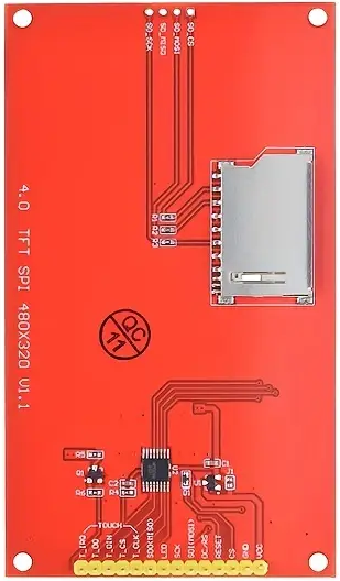
The ILI9341 4.0-inch TFT LCD display module is a versatile and vibrant display solution designed for embedded systems and microcontroller-based projects. Manufactured in China, this module features a resolution of 240x320 pixels and utilizes the ILI9341 driver IC, which supports a wide range of communication protocols, including SPI and parallel interfaces. Its compact size and high-quality display make it ideal for applications such as graphical user interfaces, data visualization, and portable devices.
Explore Projects Built with ILI9341 4.0 inch
 Open Project in Cirkit Designer
 Open Project in Cirkit Designer
 Open Project in Cirkit Designer
 Open Project in Cirkit Designer
Explore Projects Built with ILI9341 4.0 inch
Open Project in Cirkit DesignerOpen Project in Cirkit DesignerOpen Project in Cirkit DesignerOpen Project in Cirkit DesignerCommon Applications and Use Cases
- Embedded systems requiring graphical output
- DIY electronics projects
- Portable devices and handheld instruments
- Industrial control panels
- Educational and prototyping purposes
Technical Specifications
The following table outlines the key technical details of the ILI9341 4.0-inch TFT LCD module:
| Parameter | Specification |
|---|---|
| Display Type | TFT LCD |
| Driver IC | ILI9341 |
| Screen Size | 4.0 inches |
| Resolution | 240x320 pixels |
| Color Depth | 65K (16-bit RGB) |
| Interface | SPI (Serial Peripheral Interface), |
| 8/16-bit Parallel Interface | |
| Operating Voltage | 2.8V to 3.3V |
| Backlight Voltage | 3.0V to 3.6V |
| Backlight Current | 20mA to 40mA |
| Operating Temperature | -20°C to 70°C |
| Dimensions | 71.8mm x 52.7mm x 4.6mm |
Pin Configuration and Descriptions
The ILI9341 module typically has a 40-pin interface. Below is a table describing the key pins:
| Pin Number | Pin Name | Description |
|---|---|---|
| 1 | VCC | Power supply input (2.8V to 3.3V). |
| 2 | GND | Ground connection. |
| 3 | CS | Chip Select (active low). |
| 4 | RESET | Reset pin (active low). |
| 5 | DC/RS | Data/Command control pin. |
| 6 | SDI/MOSI | Serial Data Input / Master Out Slave In (SPI mode). |
| 7 | SCK | Serial Clock (SPI mode). |
| 8 | LED+ | Backlight positive terminal. |
| 9 | LED- | Backlight negative terminal. |
| 10 | IM0 | Interface mode selection pin (used to configure SPI or parallel mode). |
| 11-40 | DB0-DB15 | Data bus pins (used in parallel mode). |
Note: The exact pinout may vary depending on the specific module version. Always refer to the datasheet provided by the manufacturer.
Usage Instructions
How to Use the ILI9341 in a Circuit
- Power Supply: Connect the VCC pin to a 3.3V power source and GND to ground. Ensure the power supply is stable and within the specified range.
- Interface Selection: Configure the interface mode (SPI or parallel) by setting the IM0 pin and other related pins as per the datasheet.
- Backlight: Connect the LED+ and LED- pins to a suitable power source (3.0V to 3.6V) with a current-limiting resistor if necessary.
- Communication: For SPI mode, connect the CS, RESET, DC/RS, SDI/MOSI, and SCK pins to the corresponding pins on your microcontroller.
- Initialization: Use the appropriate initialization sequence for the ILI9341 driver IC. This typically involves sending a series of commands to configure the display.
Important Considerations and Best Practices
- Voltage Levels: Ensure all signal lines are within the 3.3V logic level. Use level shifters if interfacing with a 5V microcontroller.
- Backlight Control: Use a PWM signal to control the brightness of the backlight if required.
- Decoupling Capacitors: Place decoupling capacitors near the power pins to reduce noise and ensure stable operation.
- ESD Protection: Handle the module carefully to avoid electrostatic discharge damage.
Example: Connecting to an Arduino UNO
The ILI9341 can be connected to an Arduino UNO using SPI. Below is an example wiring diagram and code:
Wiring Diagram
| ILI9341 Pin | Arduino UNO Pin |
|---|---|
| VCC | 3.3V |
| GND | GND |
| CS | Pin 10 |
| RESET | Pin 9 |
| DC/RS | Pin 8 |
| SDI/MOSI | Pin 11 |
| SCK | Pin 13 |
| LED+ | 3.3V |
| LED- | GND |
Arduino Code Example
#include <Adafruit_GFX.h>    // Core graphics library
#include <Adafruit_ILI9341.h> // ILI9341 driver library

// Define pins for the ILI9341
#define TFT_CS 10   // Chip Select pin
#define TFT_RST 9   // Reset pin
#define TFT_DC 8    // Data/Command pin

// Create an instance of the ILI9341 display
Adafruit_ILI9341 tft = Adafruit_ILI9341(TFT_CS, TFT_DC, TFT_RST);

void setup() {
  // Initialize the display
  tft.begin();

  // Set rotation (0-3)
  tft.setRotation(1);

  // Fill the screen with a color
  tft.fillScreen(ILI9341_BLUE);

  // Display text
  tft.setTextColor(ILI9341_WHITE);
  tft.setTextSize(2);
  tft.setCursor(10, 10);
  tft.println("Hello, ILI9341!");
}

void loop() {
  // Add your code here
}
Note: Install the
Adafruit_GFXandAdafruit_ILI9341libraries in the Arduino IDE before uploading the code.
Troubleshooting and FAQs
Common Issues and Solutions
Display Not Turning On
- Verify the power supply connections and ensure the voltage is within the specified range.
- Check the backlight connections (LED+ and LED-).
No Output or Incorrect Display
- Ensure the interface mode (SPI or parallel) is configured correctly.
- Double-check the wiring and pin connections.
- Verify that the initialization sequence in the code matches the ILI9341 datasheet.
Flickering or Unstable Display
- Add decoupling capacitors near the power pins.
- Ensure the SPI clock speed is within the supported range of the ILI9341.
Partial or Distorted Graphics
- Check for loose connections or damaged wires.
- Ensure the correct resolution (240x320) is set in the code.
FAQs
Q: Can I use the ILI9341 with a 5V microcontroller?
A: Yes, but you must use level shifters to convert the 5V logic signals to 3.3V.
Q: How do I control the backlight brightness?
A: Use a PWM signal on the LED+ pin to adjust the brightness.
Q: What is the maximum SPI clock speed supported by the ILI9341?
A: The ILI9341 supports SPI clock speeds up to 10 MHz.
Q: Can I use the ILI9341 in outdoor applications?
A: The module is not sunlight-readable and is best suited for indoor use.