Cirkit Designer Logo
Cirkit Designer
Your all-in-one circuit design IDE
Home / 
Component Documentation

How to Use Orange pi 4 pro: Examples, Pinouts, and Specs

Image of Orange pi 4 pro
Cirkit Designer LogoDesign with Orange pi 4 pro in Cirkit Designer

Introduction

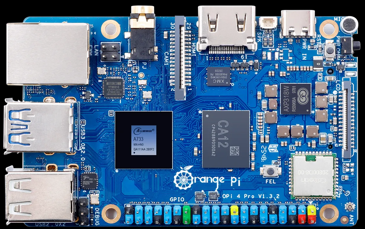
The Orange Pi 4 Pro, manufactured by Shenzhen Xunlong Software CO., Limited, is a high-performance single-board computer (SBC) designed for a wide range of applications. Powered by a quad-core ARM Cortex-A72 processor and equipped with up to 4GB of LPDDR4 RAM, this SBC offers robust computing capabilities. It features multiple connectivity options, including USB 3.0, HDMI, and Gigabit Ethernet, making it suitable for tasks such as media centers, IoT projects, AI development, and educational purposes.

Explore Projects Built with Orange pi 4 pro

Use Cirkit Designer to design, explore, and prototype these projects online. Some projects support real-time simulation. Click "Open Project" to start designing instantly!
Raspberry Pi 4B-Based Smart Health Monitoring System with GPS and GSM
Image of Accident Detection and Health Monitoring System: A project utilizing Orange pi 4 pro in a practical application
This circuit integrates a Raspberry Pi 4B with various sensors and modules, including a GPS module, a GSM module, a heart pulse sensor, an accelerometer, a barometric pressure sensor, and an OLED display. The system captures environmental data, monitors heart pulse, and can send emergency SMS alerts based on sensor readings, with power supplied by a LiPo battery and a solar panel.
Cirkit Designer LogoOpen Project in Cirkit Designer
Raspberry Pi 4B-Based GPS and GSM Tracking System with Audio Feedback
Image of unlimited range: A project utilizing Orange pi 4 pro in a practical application
This circuit features a Raspberry Pi 4B as the central processing unit, interfaced with a GPS NEO-6M V2 module for location tracking and an Adafruit FONA 808 Shield for cellular communication. It includes a PAM8406 5V Digital Audio Amplifier connected to an Adafruit STEMMA Speaker for audio output, and a Condenser Microphone connected to the FONA 808 for audio input. Power management is handled by a 12V battery connected to a voltage regulator that steps down the voltage to 5V and 3V required by the various components.
Cirkit Designer LogoOpen Project in Cirkit Designer
Raspberry Pi 4B-Based Current Monitoring System with I2C OLED Display
Image of Virtual Energy Monitoring Circuit: A project utilizing Orange pi 4 pro in a practical application
This circuit features a Raspberry Pi 4B as the central processing unit, interfaced with an Adafruit ADS1115 16-bit I2C ADC for analog-to-digital conversion and a 0.96" OLED display for visual output. The ADS1115 is connected to a current sensor for measuring electrical current, with the sensor's output and burden pins connected to the ADC's analog input channels. The Raspberry Pi communicates with both the ADC and the OLED display over the I2C bus, using its GPIO2 and GPIO3 pins for data (SDA) and clock (SCL) lines, respectively.
Cirkit Designer LogoOpen Project in Cirkit Designer
Raspberry Pi 4B with I2C Current Sensing and OLED Display
Image of iot task 2: A project utilizing Orange pi 4 pro in a practical application
This circuit features a Raspberry Pi 4B as the central processing unit, interfaced with an Adafruit ADS1115 16-bit I2C ADC for analog-to-digital conversion and a 0.96" OLED display for visual output. The ADC is connected to a current sensor for measuring electrical current, with the sensor's output connected to the ADC's AIN0 pin and the burden resistor connected to AIN1. The Raspberry Pi communicates with both the ADC and the OLED display over the I2C bus, using GPIO2 (SDA) and GPIO3 (SCL) for data exchange.
Cirkit Designer LogoOpen Project in Cirkit Designer

Explore Projects Built with Orange pi 4 pro

Use Cirkit Designer to design, explore, and prototype these projects online. Some projects support real-time simulation. Click "Open Project" to start designing instantly!
Image of Accident Detection and Health Monitoring System: A project utilizing Orange pi 4 pro in a practical application
Raspberry Pi 4B-Based Smart Health Monitoring System with GPS and GSM
This circuit integrates a Raspberry Pi 4B with various sensors and modules, including a GPS module, a GSM module, a heart pulse sensor, an accelerometer, a barometric pressure sensor, and an OLED display. The system captures environmental data, monitors heart pulse, and can send emergency SMS alerts based on sensor readings, with power supplied by a LiPo battery and a solar panel.
Cirkit Designer LogoOpen Project in Cirkit Designer
Image of unlimited range: A project utilizing Orange pi 4 pro in a practical application
Raspberry Pi 4B-Based GPS and GSM Tracking System with Audio Feedback
This circuit features a Raspberry Pi 4B as the central processing unit, interfaced with a GPS NEO-6M V2 module for location tracking and an Adafruit FONA 808 Shield for cellular communication. It includes a PAM8406 5V Digital Audio Amplifier connected to an Adafruit STEMMA Speaker for audio output, and a Condenser Microphone connected to the FONA 808 for audio input. Power management is handled by a 12V battery connected to a voltage regulator that steps down the voltage to 5V and 3V required by the various components.
Cirkit Designer LogoOpen Project in Cirkit Designer
Image of Virtual Energy Monitoring Circuit: A project utilizing Orange pi 4 pro in a practical application
Raspberry Pi 4B-Based Current Monitoring System with I2C OLED Display
This circuit features a Raspberry Pi 4B as the central processing unit, interfaced with an Adafruit ADS1115 16-bit I2C ADC for analog-to-digital conversion and a 0.96" OLED display for visual output. The ADS1115 is connected to a current sensor for measuring electrical current, with the sensor's output and burden pins connected to the ADC's analog input channels. The Raspberry Pi communicates with both the ADC and the OLED display over the I2C bus, using its GPIO2 and GPIO3 pins for data (SDA) and clock (SCL) lines, respectively.
Cirkit Designer LogoOpen Project in Cirkit Designer
Image of iot task 2: A project utilizing Orange pi 4 pro in a practical application
Raspberry Pi 4B with I2C Current Sensing and OLED Display
This circuit features a Raspberry Pi 4B as the central processing unit, interfaced with an Adafruit ADS1115 16-bit I2C ADC for analog-to-digital conversion and a 0.96" OLED display for visual output. The ADC is connected to a current sensor for measuring electrical current, with the sensor's output connected to the ADC's AIN0 pin and the burden resistor connected to AIN1. The Raspberry Pi communicates with both the ADC and the OLED display over the I2C bus, using GPIO2 (SDA) and GPIO3 (SCL) for data exchange.
Cirkit Designer LogoOpen Project in Cirkit Designer

Common Applications

  • Media Centers: Stream and play high-definition video content.
  • IoT Projects: Serve as a hub for Internet of Things devices.
  • AI and Machine Learning: Run lightweight AI models and edge computing tasks.
  • Educational Use: Teach programming, electronics, and system design.
  • Home Automation: Control smart home devices and systems.

Technical Specifications

Key Technical Details

Specification Details
Processor Rockchip RK3399 (Dual Cortex-A72 @ 2.0GHz + Quad Cortex-A53 @ 1.5GHz)
GPU ARM Mali-T860 MP4
RAM 4GB LPDDR4
Storage eMMC (16GB/32GB/64GB options) and microSD card slot
Connectivity Gigabit Ethernet, Wi-Fi 802.11ac, Bluetooth 5.0
USB Ports 1x USB 3.0, 2x USB 2.0, 1x USB Type-C (OTG and power delivery)
Video Output HDMI 2.0 (4K@60Hz), MIPI-DSI
Audio Output HDMI, 3.5mm audio jack
Power Supply 5V/3A via USB Type-C
Operating Systems Android, Debian, Ubuntu, and other Linux distributions
GPIO 40-pin GPIO header (compatible with Raspberry Pi GPIO layout)
Dimensions 90mm x 64mm

Pin Configuration and Descriptions

The Orange Pi 4 Pro features a 40-pin GPIO header, which is compatible with the Raspberry Pi GPIO layout. Below is the pinout description:

Pin Name Description
1 3.3V Power (3.3V)
2 5V Power (5V)
3 GPIO2 (SDA1) I2C Data Line
4 5V Power (5V)
5 GPIO3 (SCL1) I2C Clock Line
6 GND Ground
7 GPIO4 General Purpose I/O
8 GPIO14 (TXD0) UART Transmit
9 GND Ground
10 GPIO15 (RXD0) UART Receive
... ... ...
39 GND Ground
40 GPIO21 General Purpose I/O

For the full GPIO pinout, refer to the official Orange Pi 4 Pro documentation.


Usage Instructions

How to Use the Orange Pi 4 Pro in a Circuit

  1. Powering the Board: Use a 5V/3A power adapter with a USB Type-C connector to power the board. Ensure the power supply is stable to avoid damage.
  2. Connecting Peripherals: Attach peripherals such as a keyboard, mouse, and monitor via USB and HDMI ports. For headless operation, connect via SSH over Ethernet or Wi-Fi.
  3. Booting the OS: Flash a compatible operating system (e.g., Debian or Ubuntu) onto a microSD card or eMMC storage. Insert the microSD card into the slot and power on the board.
  4. GPIO Usage: Use the 40-pin GPIO header for interfacing with sensors, actuators, and other devices. Libraries such as RPi.GPIO (Python) or WiringPi can be used for programming the GPIO pins.

Important Considerations

  • Cooling: The RK3399 processor can generate significant heat under load. Use a heatsink or active cooling (fan) for optimal performance.
  • Power Supply: Ensure the power supply meets the 5V/3A requirement to prevent instability.
  • Static Protection: Handle the board with care to avoid electrostatic discharge (ESD) damage.
  • OS Compatibility: Verify that the operating system you choose supports the features you need.

Example: Blinking an LED with GPIO and Python

Below is an example of how to blink an LED connected to GPIO pin 7 using Python:


Import the required library

import RPi.GPIO as GPIO import time

Pin configuration

LED_PIN = 7 # GPIO pin number where the LED is connected

GPIO setup

GPIO.setmode(GPIO.BOARD) # Use physical pin numbering GPIO.setup(LED_PIN, GPIO.OUT) # Set the pin as an output

try: while True: GPIO.output(LED_PIN, GPIO.HIGH) # Turn the LED on time.sleep(1) # Wait for 1 second GPIO.output(LED_PIN, GPIO.LOW) # Turn the LED off time.sleep(1) # Wait for 1 second except KeyboardInterrupt: # Clean up GPIO settings on exit GPIO.cleanup()


**Note**: Install the `RPi.GPIO` library on your Orange Pi 4 Pro before running the code.

---

Troubleshooting and FAQs

Common Issues

  1. Board Does Not Power On:

    • Ensure the power supply provides 5V/3A and is connected securely.
    • Check the USB Type-C cable for damage or poor quality.
  2. No Display Output:

    • Verify the HDMI cable and monitor are functioning correctly.
    • Ensure the operating system is properly flashed onto the storage device.
  3. Overheating:

    • Install a heatsink or fan to improve cooling.
    • Avoid running the board in enclosed spaces without ventilation.
  4. GPIO Pins Not Working:

    • Double-check the pin configuration and connections.
    • Ensure the GPIO library is installed and configured correctly.

FAQs

  • Q: Can I use Raspberry Pi HATs with the Orange Pi 4 Pro?
    A: Yes, the 40-pin GPIO header is compatible with most Raspberry Pi HATs, but software support may vary.

  • Q: What operating systems are supported?
    A: The Orange Pi 4 Pro supports Android, Debian, Ubuntu, and other Linux distributions.

  • Q: How do I enable Wi-Fi?
    A: Use the network manager in your operating system to scan and connect to Wi-Fi networks.

  • Q: Can I power the board via GPIO pins?
    A: Yes, you can supply 5V directly to the 5V GPIO pins, but ensure proper polarity and voltage regulation.

For additional support, refer to the official Orange Pi 4 Pro documentation or community forums.