Cirkit Designer Logo
Cirkit Designer
Your all-in-one circuit design IDE
Home / 
Component Documentation

How to Use PIR sensor: Examples, Pinouts, and Specs

Image of PIR sensor
Cirkit Designer LogoDesign with PIR sensor in Cirkit Designer

Introduction

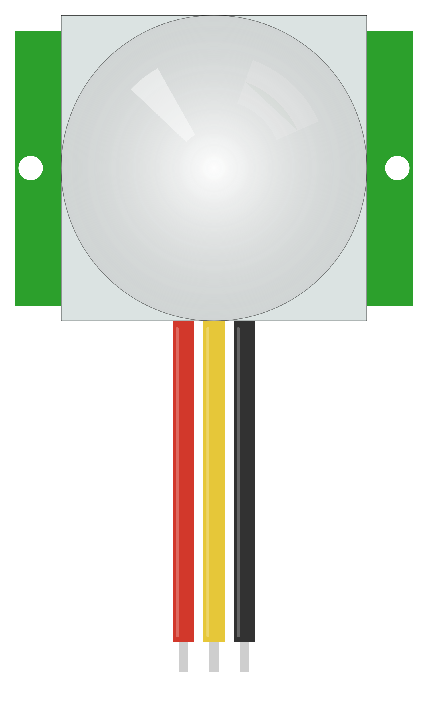
A Passive Infrared (PIR) sensor is an electronic device that measures infrared (IR) light radiating from objects within its field of view. They are most often used in PIR-based motion detectors for applications such as security alarms, automatic lighting control, and energy efficiency systems. PIR sensors detect the movement of heat-emitting bodies, such as humans or animals, by sensing changes in the infrared spectrum.

Explore Projects Built with PIR sensor

Use Cirkit Designer to design, explore, and prototype these projects online. Some projects support real-time simulation. Click "Open Project" to start designing instantly!
Arduino UNO with PIR Sensor and Bluetooth Connectivity
Image of smart home security system: A project utilizing PIR sensor in a practical application
This circuit features an Arduino UNO connected to a PIR (Passive Infrared) sensor and an HC-05 Bluetooth module. The PIR sensor detects motion and sends a signal to the Arduino, which then communicates via Bluetooth using the HC-05 module. The embedded code on the Arduino is configured to send a specific message over serial when motion is detected by the PIR sensor.
Cirkit Designer LogoOpen Project in Cirkit Designer
Arduino UNO-Based Motion Detection System with PIR Sensor
Image of pir: A project utilizing PIR sensor in a practical application
This circuit consists of an Arduino UNO microcontroller connected to a PIR sensor. The PIR sensor is powered by the Arduino's 5V and GND pins, and its signal output is connected to the Arduino's digital pin D2. The setup is likely intended for motion detection applications.
Cirkit Designer LogoOpen Project in Cirkit Designer
Arduino UNO-Based Motion Detection System with Bluetooth Connectivity
Image of iot: A project utilizing PIR sensor in a practical application
This circuit features an Arduino UNO connected to a PIR (Passive Infrared) sensor and a Bluetooth module. The PIR sensor's signal pin is connected to the Arduino's digital pin D7 to detect motion, and the Bluetooth module is interfaced through the Arduino's serial pins D0 (RX) and D1 (TX) for wireless communication. The Arduino is programmed to send a specific signal over Bluetooth when motion is detected by the PIR sensor.
Cirkit Designer LogoOpen Project in Cirkit Designer
Arduino UNO PIR Motion Sensor Interface
Image of Interfacing PIR Sensor With Arduino UNO To Detect Motion: A project utilizing PIR sensor in a practical application
This circuit connects a PIR (Passive Infrared) sensor to an Arduino UNO microcontroller to detect motion. When the PIR sensor detects motion, the Arduino activates an LED on pin D13 and sends a notification to the serial monitor. The circuit is designed for applications requiring motion detection, such as security systems or automated lighting.
Cirkit Designer LogoOpen Project in Cirkit Designer

Explore Projects Built with PIR sensor

Use Cirkit Designer to design, explore, and prototype these projects online. Some projects support real-time simulation. Click "Open Project" to start designing instantly!
Image of smart home security system: A project utilizing PIR sensor in a practical application
Arduino UNO with PIR Sensor and Bluetooth Connectivity
This circuit features an Arduino UNO connected to a PIR (Passive Infrared) sensor and an HC-05 Bluetooth module. The PIR sensor detects motion and sends a signal to the Arduino, which then communicates via Bluetooth using the HC-05 module. The embedded code on the Arduino is configured to send a specific message over serial when motion is detected by the PIR sensor.
Cirkit Designer LogoOpen Project in Cirkit Designer
Image of pir: A project utilizing PIR sensor in a practical application
Arduino UNO-Based Motion Detection System with PIR Sensor
This circuit consists of an Arduino UNO microcontroller connected to a PIR sensor. The PIR sensor is powered by the Arduino's 5V and GND pins, and its signal output is connected to the Arduino's digital pin D2. The setup is likely intended for motion detection applications.
Cirkit Designer LogoOpen Project in Cirkit Designer
Image of iot: A project utilizing PIR sensor in a practical application
Arduino UNO-Based Motion Detection System with Bluetooth Connectivity
This circuit features an Arduino UNO connected to a PIR (Passive Infrared) sensor and a Bluetooth module. The PIR sensor's signal pin is connected to the Arduino's digital pin D7 to detect motion, and the Bluetooth module is interfaced through the Arduino's serial pins D0 (RX) and D1 (TX) for wireless communication. The Arduino is programmed to send a specific signal over Bluetooth when motion is detected by the PIR sensor.
Cirkit Designer LogoOpen Project in Cirkit Designer
Image of Interfacing PIR Sensor With Arduino UNO To Detect Motion: A project utilizing PIR sensor in a practical application
Arduino UNO PIR Motion Sensor Interface
This circuit connects a PIR (Passive Infrared) sensor to an Arduino UNO microcontroller to detect motion. When the PIR sensor detects motion, the Arduino activates an LED on pin D13 and sends a notification to the serial monitor. The circuit is designed for applications requiring motion detection, such as security systems or automated lighting.
Cirkit Designer LogoOpen Project in Cirkit Designer

Technical Specifications

Key Technical Details

  • Operating Voltage: Typically 5V to 12V DC
  • Idle Current: <50uA
  • Output Voltage: High/Low (3.3V TTL can be directly connected to microcontrollers)
  • Detection Range: Up to 7 meters (adjustable)
  • Detection Angle: Up to 120 degrees
  • Warm-Up Time: Approximately 20-60 seconds
  • Output Delay: Adjustable, from 5 seconds to 5 minutes

Pin Configuration and Descriptions

Pin Number Name Description
1 VCC Power supply input (5V-12V DC)
2 OUT Digital output pin (High/Low)
3 GND Ground connection

Usage Instructions

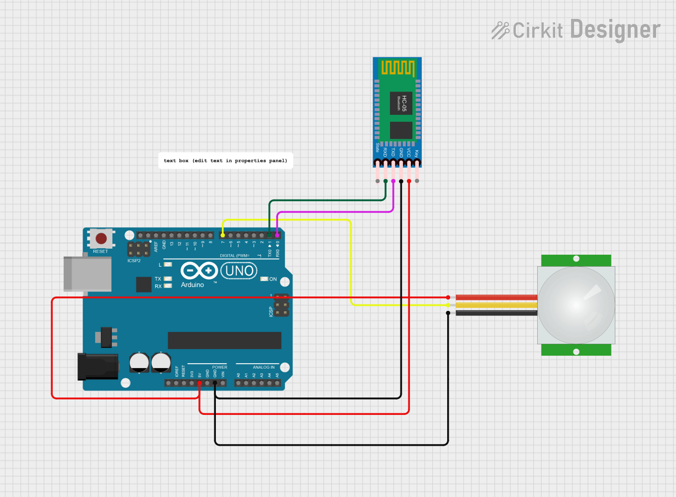
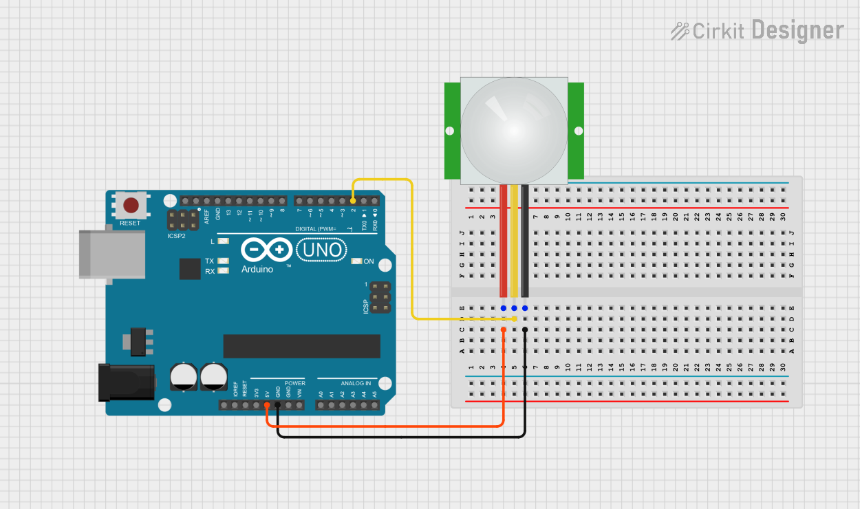
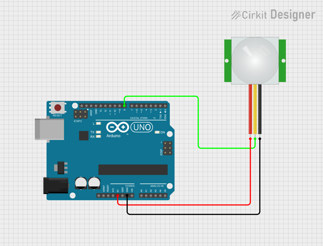
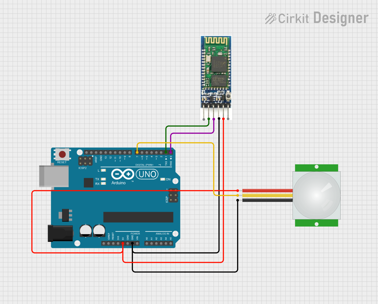
Connecting to a Circuit

  1. Connect the VCC pin to the positive power supply (5V-12V DC).
  2. Connect the OUT pin to a digital input pin on a microcontroller.
  3. Connect the GND pin to the ground of the power supply and microcontroller.

Important Considerations and Best Practices

  • Ensure that the sensor is placed in an area where it can have a clear view of the area to be monitored.
  • Avoid placing the sensor near heat sources or in direct sunlight to prevent false triggers.
  • Adjust the sensitivity and time delay according to the specific requirements of your application.
  • Use appropriate pull-up or pull-down resistors on the OUT pin if required by your microcontroller.

Example Code for Arduino UNO

// Define the PIR sensor pin
const int PIRPin = 2; // Connect PIR sensor's OUT pin to digital pin 2

void setup() {
  pinMode(PIRPin, INPUT); // Initialize the PIR sensor pin as an input
  Serial.begin(9600);    // Start serial communication at 9600 baud rate
}

void loop() {
  int motionStatus = digitalRead(PIRPin); // Read the PIR sensor's output

  if (motionStatus == HIGH) {
    // When motion is detected, the output pin goes HIGH
    Serial.println("Motion detected!");
    // Add code here to handle the motion detection event
  } else {
    // When no motion is detected, the output pin stays LOW
    Serial.println("No motion detected.");
  }

  delay(100); // Wait for 100 milliseconds before reading again
}

Troubleshooting and FAQs

Common Issues

  • False Triggers: Adjust the sensitivity and delay settings. Ensure the sensor is not facing any heat sources or exposed to direct sunlight.
  • No Response: Check the power supply and connections. Ensure the sensor has warmed up for the specified time.
  • Intermittent Operation: Verify that the sensor is not in a high-traffic area where continuous movement is present.

Solutions and Tips for Troubleshooting

  • Double-check wiring and connections for any loose contacts.
  • Test the sensor with a simple LED circuit to confirm its operation before connecting to a microcontroller.
  • Use serial print statements in your code to debug and understand the sensor's output.

FAQs

Q: Can the PIR sensor work through glass? A: No, most PIR sensors cannot detect motion through glass as it blocks the infrared waves.

Q: How can I adjust the sensitivity and time delay? A: Many PIR sensors come with potentiometers that allow you to adjust sensitivity and time delay.

Q: Is it possible to power the PIR sensor with a battery? A: Yes, as long as the battery provides a voltage within the sensor's operating range (typically 5V-12V DC).

Q: How long does the PIR sensor need to warm up? A: PIR sensors typically require 20-60 seconds to stabilize after being powered on.

Remember, this documentation is a starting point for working with PIR sensors. Always consult the specific datasheet for your sensor model for the most accurate information.