How to Use Hall Effect Current Sensor: Examples, Pinouts, and Specs
Introduction
The Hall Effect Current Sensor is a device that measures the current flowing through a conductor by detecting the magnetic field generated by the current. It provides an electrical output proportional to the current, enabling precise and non-invasive current measurement. These sensors are widely used in applications requiring current monitoring, protection, and control.
Explore Projects Built with Hall Effect Current Sensor


Explore Projects Built with Hall Effect Current Sensor
Common Applications and Use Cases
- Motor control and monitoring in industrial systems
- Battery management systems (BMS) in electric vehicles
- Power supply monitoring in renewable energy systems
- Overcurrent protection in electronic circuits
- Energy metering and load monitoring
Technical Specifications
Below are the general technical specifications for a typical Hall Effect Current Sensor. Note that specific models may vary, so always refer to the datasheet of the exact sensor you are using.
Key Specifications
- Supply Voltage (Vcc): 3.3V to 5V
- Current Measurement Range: ±20A to ±100A (varies by model)
- Output Voltage Range: 0.5V to 4.5V (proportional to current)
- Sensitivity: 66mV/A (example for a ±30A sensor)
- Accuracy: ±1% (typical)
- Response Time: <5 µs
- Operating Temperature Range: -40°C to +85°C
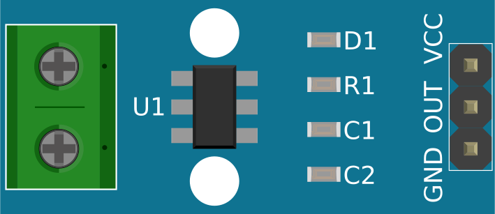
Pin Configuration and Descriptions
The Hall Effect Current Sensor typically comes with three or more pins. Below is a general pinout description:
| Pin | Name | Description |
|---|---|---|
| 1 | Vcc | Power supply input (3.3V or 5V, depending on the sensor model). |
| 2 | GND | Ground connection. |
| 3 | Vout | Analog output voltage proportional to the measured current. |
| 4 | (Optional) NC | Not connected or reserved for additional features (varies by model). |
Usage Instructions
How to Use the Component in a Circuit
Power the Sensor:
- Connect the Vcc pin to a 3.3V or 5V power supply, depending on the sensor's specifications.
- Connect the GND pin to the ground of your circuit.
Connect the Conductor:
- Pass the conductor carrying the current to be measured through the sensor's aperture (if applicable).
- For PCB-mounted sensors, connect the current-carrying wire to the designated input and output terminals.
Read the Output:
- The Vout pin provides an analog voltage proportional to the current flowing through the conductor.
- Use an ADC (Analog-to-Digital Converter) on a microcontroller (e.g., Arduino) to read the voltage and calculate the current.
Important Considerations and Best Practices
- Calibration: Some sensors may require calibration to ensure accurate readings. Refer to the datasheet for calibration procedures.
- Noise Filtering: Use capacitors or software filtering to reduce noise in the output signal.
- Current Range: Ensure the sensor's current range matches your application's requirements to avoid saturation or damage.
- Orientation: For sensors with apertures, ensure the conductor is properly aligned with the sensor's magnetic field detection axis.
- Temperature Effects: Be aware of temperature-induced drift in the sensor's output and compensate if necessary.
Example: Using the Sensor with an Arduino UNO
Below is an example of how to interface a Hall Effect Current Sensor with an Arduino UNO to measure current.
// Example code for interfacing a Hall Effect Current Sensor with Arduino UNO
// This example assumes a sensor with a sensitivity of 66mV/A and a 5V supply.

const int sensorPin = A0; // Analog pin connected to the sensor's Vout
const float sensitivity = 0.066; // Sensor sensitivity in V/A (66mV/A)
const float Vcc = 5.0; // Supply voltage to the sensor
const float zeroCurrentVoltage = Vcc / 2; // Output voltage at 0A (midpoint)

void setup() {
  Serial.begin(9600); // Initialize serial communication
}

void loop() {
  int sensorValue = analogRead(sensorPin); // Read the analog value from the sensor
  float voltage = sensorValue * (Vcc / 1023.0); // Convert ADC value to voltage
  float current = (voltage - zeroCurrentVoltage) / sensitivity;
  // Calculate current in Amperes

  Serial.print("Current: ");
  Serial.print(current, 2); // Print current with 2 decimal places
  Serial.println(" A"); // Append unit

  delay(500); // Wait for 500ms before the next reading
}
Troubleshooting and FAQs
Common Issues and Solutions
No Output or Incorrect Readings:
- Cause: Incorrect wiring or power supply voltage.
- Solution: Double-check the connections and ensure the sensor is powered with the correct voltage.
Output Voltage Does Not Change:
- Cause: Current range of the sensor is too high for the measured current.
- Solution: Use a sensor with a lower current range for better sensitivity.
Noisy Output Signal:
- Cause: Electromagnetic interference or insufficient filtering.
- Solution: Add a decoupling capacitor (e.g., 0.1 µF) between Vcc and GND, and use software filtering.
Temperature Drift:
- Cause: Sensor output varies with temperature.
- Solution: Implement temperature compensation in your software or use a sensor with built-in compensation.
FAQs
Q: Can I use the Hall Effect Current Sensor to measure AC current?
A: Yes, Hall Effect Current Sensors can measure both AC and DC currents. Ensure your circuit and microcontroller can handle the sensor's output signal.
Q: How do I calculate the current from the sensor's output voltage?
A: Use the formula:
Current (A) = (Vout - Vzero) / Sensitivity
Where Vout is the sensor's output voltage, Vzero is the output voltage at 0A, and Sensitivity is the sensor's sensitivity in V/A.
Q: Can I use this sensor with a 3.3V microcontroller?
A: Yes, as long as the sensor supports a 3.3V supply and the output voltage range is compatible with the microcontroller's ADC input.
Q: What happens if the current exceeds the sensor's range?
A: The sensor may saturate, and the output voltage will no longer be proportional to the current. Prolonged overcurrent may damage the sensor. Always choose a sensor with an appropriate current range for your application.