How to Use ZERO CROSSING DETECTOR: Examples, Pinouts, and Specs
Introduction
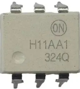
The Zero Crossing Detector (H11AA1), manufactured by anon, is an optocoupler-based component designed to detect the point where an AC voltage waveform crosses zero volts. This detection is crucial for applications requiring precise timing and synchronization with AC signals. The H11AA1 is widely used in phase-locked loops, timing circuits, motor control systems, and triggering devices like TRIACs or SCRs in AC power control.
By isolating the input and output through an optocoupler, the H11AA1 ensures electrical safety and noise immunity, making it ideal for interfacing low-voltage control circuits with high-voltage AC systems.
Explore Projects Built with ZERO CROSSING DETECTOR
Explore Projects Built with ZERO CROSSING DETECTOR
Technical Specifications
Key Technical Details
- Manufacturer Part ID: H11AA1
- Input Voltage (LED Forward Voltage): 1.2V (typical), 1.5V (maximum)
- Input Current (LED Forward Current): 10mA (typical), 60mA (maximum)
- Output Voltage (Collector-Emitter Voltage): 30V (maximum)
- Output Current (Collector Current): 50mA (maximum)
- Isolation Voltage: 5300 VRMS (minimum)
- Operating Temperature Range: -55°C to +100°C
- Package Type: 6-pin DIP
Pin Configuration and Descriptions
The H11AA1 has a 6-pin configuration, as detailed below:
| Pin Number | Pin Name | Description |
|---|---|---|
| 1 | Anode (LED1) | Positive terminal of the first internal LED. Connect to the AC signal source. |
| 2 | Cathode (LED1) | Negative terminal of the first internal LED. Connect to the AC signal source. |
| 3 | Cathode (LED2) | Negative terminal of the second internal LED. Connect to the AC signal source. |
| 4 | Anode (LED2) | Positive terminal of the second internal LED. Connect to the AC signal source. |
| 5 | Emitter (Transistor) | Output terminal of the optocoupler's phototransistor. |
| 6 | Collector (Transistor) | Output terminal of the optocoupler's phototransistor. |
Internal Schematic
The H11AA1 contains two LEDs connected in reverse parallel to handle both positive and negative half-cycles of an AC signal. The LEDs are optically coupled to a phototransistor, which provides the output signal.
Usage Instructions
How to Use the Component in a Circuit
Input Connection:
- Connect the AC signal to pins 1 (Anode of LED1) and 2 (Cathode of LED1).
- Pins 3 and 4 (LED2) are connected in reverse polarity to handle the opposite phase of the AC signal.
- Use a current-limiting resistor in series with the AC signal to limit the current through the LEDs. The resistor value can be calculated using Ohm's law: [ R = \frac{V_{AC} - V_f}{I_f} ] where (V_{AC}) is the AC voltage, (V_f) is the forward voltage of the LED (1.2V typical), and (I_f) is the desired forward current (e.g., 10mA).
Output Connection:
- Connect the phototransistor's collector (pin 6) to the positive supply voltage (e.g., 5V).
- Connect the emitter (pin 5) to ground through a pull-down resistor (e.g., 10kΩ). The output signal will be a square wave synchronized with the zero crossings of the AC input.
Interfacing with a Microcontroller:
- The output signal from the phototransistor can be fed directly to a microcontroller's digital input pin.
- Use the microcontroller to detect the rising or falling edges of the square wave to determine the zero-crossing points.
Important Considerations and Best Practices
- Isolation: Ensure proper isolation between the high-voltage AC side and the low-voltage control side to prevent damage to sensitive components.
- Resistor Selection: Choose appropriate resistor values to limit the current through the LEDs and ensure reliable operation.
- Filtering: Add a small capacitor (e.g., 0.1µF) across the output to filter noise and improve signal stability.
- Temperature: Operate the component within the specified temperature range to avoid performance degradation.
Example: Interfacing with Arduino UNO
Below is an example of how to use the H11AA1 with an Arduino UNO to detect zero crossings:
// Pin configuration
const int zeroCrossingPin = 2; // Digital pin connected to H11AA1 output
volatile bool zeroCrossDetected = false;

// Interrupt service routine for zero-crossing detection
void zeroCrossISR() {
  zeroCrossDetected = true; // Set flag when zero crossing is detected
}

void setup() {
  pinMode(zeroCrossingPin, INPUT); // Set pin as input
  attachInterrupt(digitalPinToInterrupt(zeroCrossingPin), zeroCrossISR, RISING);
  Serial.begin(9600); // Initialize serial communication
}

void loop() {
  if (zeroCrossDetected) {
    zeroCrossDetected = false; // Clear the flag
    Serial.println("Zero crossing detected!"); // Print message
  }
}
Troubleshooting and FAQs
Common Issues and Solutions
No Output Signal:
- Cause: Incorrect resistor value or no current-limiting resistor.
- Solution: Verify the resistor value and ensure it limits the current to within the LED's specifications.
Output Signal is Noisy:
- Cause: Electrical noise or insufficient filtering.
- Solution: Add a small capacitor (e.g., 0.1µF) across the output to filter noise.
Microcontroller Not Detecting Zero Crossings:
- Cause: Incorrect pin configuration or missing pull-down resistor.
- Solution: Verify the microcontroller pin configuration and ensure a pull-down resistor is connected to the output.
Component Overheating:
- Cause: Excessive current through the LEDs.
- Solution: Check the current-limiting resistor and ensure the current is within the specified range.
FAQs
Q: Can the H11AA1 handle DC signals?
A: No, the H11AA1 is designed for AC signals. It relies on the alternating polarity of the AC waveform to operate correctly.Q: What is the maximum AC voltage the H11AA1 can handle?
A: The maximum AC voltage depends on the current-limiting resistor. Ensure the resistor value limits the LED current to within the specified range.Q: Can I use the H11AA1 for phase angle control?
A: Yes, the H11AA1 can be used to detect zero crossings, which is essential for phase angle control in AC power applications.Q: Is the H11AA1 suitable for 50Hz and 60Hz AC signals?
A: Yes, the H11AA1 works with both 50Hz and 60Hz AC signals.