
How to Use Intel Edison Mini Breakout Board (Bottom View): Examples, Pinouts, and Specs
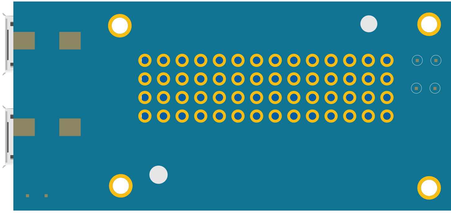
 Design with Intel Edison Mini Breakout Board (Bottom View) in Cirkit Designer
Introduction
The Intel Edison Mini Breakout Board is a compact development platform designed to support the Intel Edison module. It is tailored for Internet of Things (IoT) applications, offering a small form factor and easy access to the module's I/O pins. This board simplifies prototyping and integration with sensors, actuators, and other peripherals, making it ideal for developers working on smart devices, wearables, and connected systems.
Explore Projects Built with Intel Edison Mini Breakout Board (Bottom View)
 Open Project in Cirkit Designer
 Open Project in Cirkit Designer
 Open Project in Cirkit Designer
 Open Project in Cirkit Designer
Explore Projects Built with Intel Edison Mini Breakout Board (Bottom View)
Open Project in Cirkit DesignerOpen Project in Cirkit DesignerOpen Project in Cirkit DesignerOpen Project in Cirkit DesignerCommon Applications and Use Cases
- IoT prototyping and development
- Wearable technology
- Smart home devices
- Robotics and automation
- Sensor integration and data acquisition
Technical Specifications
The Intel Edison Mini Breakout Board provides essential features to support the Intel Edison module. Below are the key technical details:
Key Technical Details
- Power Supply Voltage: 7V to 15V (via DC jack) or 3.3V (via breakout pins)
- Input/Output Voltage Levels: 1.8V logic
- USB Ports:
- 1x USB OTG (Micro-AB)
- 1x USB to UART (Micro-B)
- GPIO Pins: 40 GPIOs (1.8V logic level)
- Communication Protocols: UART, I2C, SPI, PWM
- Dimensions: 35.5mm x 25mm
- Operating Temperature: 0°C to 40°C
Pin Configuration and Descriptions
The Intel Edison Mini Breakout Board provides access to the Intel Edison module's I/O pins through two 70-pin connectors. Below is a summary of the key pin configurations:
Power and Ground Pins
| Pin Name | Description | Voltage Level |
|---|---|---|
| VIN | Input power supply | 7V to 15V |
| V3.3 | 3.3V power output | 3.3V |
| GND | Ground | 0V |
Communication Pins
| Pin Name | Description | Protocol |
|---|---|---|
| TX | UART Transmit | UART |
| RX | UART Receive | UART |
| SCL | I2C Clock | I2C |
| SDA | I2C Data | I2C |
| MOSI | SPI Master Out, Slave In | SPI |
| MISO | SPI Master In, Slave Out | SPI |
| SCK | SPI Clock | SPI |
GPIO Pins
| Pin Name | Description | Voltage Level |
|---|---|---|
| GPIO0 | General Purpose I/O | 1.8V |
| GPIO1 | General Purpose I/O | 1.8V |
| GPIO2 | General Purpose I/O | 1.8V |
| ... | ... | ... |
Usage Instructions
How to Use the Component in a Circuit
- Powering the Board:
- Connect a 7V to 15V DC power supply to the VIN pin or DC jack.
- Alternatively, supply 3.3V directly to the V3.3 pin.
- Connecting Peripherals:
- Use the GPIO pins to connect sensors, actuators, or other devices.
- Ensure all connected devices operate at 1.8V logic levels or use level shifters.
- Programming the Edison Module:
- Connect the board to a computer via the USB to UART (Micro-B) port.
- Use the Arduino IDE or Intel's development tools to upload code.
- Using Communication Protocols:
- Utilize the I2C, SPI, or UART pins to interface with external devices.
Important Considerations and Best Practices
- Voltage Levels: The GPIO pins operate at 1.8V logic. Use level shifters for devices that operate at higher voltages.
- Heat Management: Ensure proper ventilation to prevent overheating during operation.
- USB OTG: Use the USB OTG port for connecting USB devices or debugging.
- Pin Protection: Avoid shorting pins or exceeding voltage/current ratings to prevent damage.
Example: Connecting to an Arduino UNO
To interface the Intel Edison Mini Breakout Board with an Arduino UNO, use level shifters to match the 1.8V logic of the Edison with the 5V logic of the Arduino. Below is an example of using I2C communication:
Arduino Code Example
#include <Wire.h> // Include the Wire library for I2C communication

void setup() {
  Wire.begin(); // Initialize I2C communication
  Serial.begin(9600); // Start serial communication for debugging
  Serial.println("I2C communication initialized.");
}

void loop() {
  Wire.beginTransmission(0x08); // Start communication with device at address 0x08
  Wire.write("Hello, Edison!"); // Send data to the Intel Edison
  Wire.endTransmission(); // End the transmission

  delay(1000); // Wait for 1 second before sending again
}
Troubleshooting and FAQs
Common Issues and Solutions
Board Not Powering On:
- Ensure the power supply voltage is within the specified range (7V to 15V or 3.3V).
- Check all connections for loose wires or shorts.
USB Connection Not Recognized:
- Verify that the correct drivers for the Intel Edison are installed on your computer.
- Use a different USB cable or port to rule out hardware issues.
GPIO Pins Not Responding:
- Confirm that the connected devices operate at 1.8V logic levels.
- Check the code for proper pin initialization.
Overheating:
- Ensure adequate ventilation and avoid operating the board in high-temperature environments.
FAQs
Q: Can I power the board using a USB connection?
A: No, the USB ports on the Mini Breakout Board are for data communication only. Use the VIN or V3.3 pins for power.
Q: What development tools are compatible with the Intel Edison?
A: The Intel Edison supports the Arduino IDE, Intel XDK, and other Linux-based development tools.
Q: How do I reset the board?
A: Press and hold the reset button on the board for a few seconds to restart the Intel Edison module.
Q: Can I use 5V sensors directly with the GPIO pins?
A: No, the GPIO pins operate at 1.8V logic. Use level shifters to interface with 5V sensors.