How to Use 12v DC fan: Examples, Pinouts, and Specs
Introduction
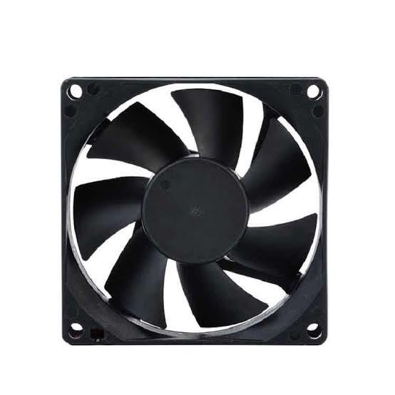
The 12V DC fan is an essential component widely used in various cooling applications. It operates on direct current and is designed to maintain a low temperature in electronic devices, preventing overheating that can lead to performance issues or hardware damage. Common applications include computer cases, power supplies, amplifiers, and any other equipment requiring active cooling.
Explore Projects Built with 12v DC fan


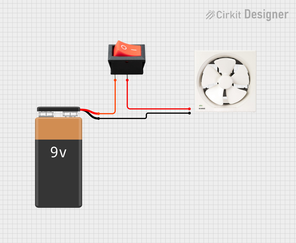

Explore Projects Built with 12v DC fan
Technical Specifications
General Features
- Operating Voltage: 12V DC
- Typical Current: Varies with model (e.g., 0.15A)
- Power Consumption: Varies with model (e.g., 1.8W)
- Bearing Type: Sleeve/Ball
- Fan Speed: Varies with model (e.g., 2000 RPM)
- Airflow: Varies with model (e.g., 53 CFM)
- Noise Level: Varies with model (e.g., 25 dBA)
- Lifespan: Varies with model (e.g., 30,000 hours)
Pin Configuration and Descriptions
| Pin Number | Description | Notes |
|---|---|---|
| 1 | Ground | Connect to system ground |
| 2 | +12V DC Supply | Connect to 12V power source |
| 3 | Tachometer Signal | Optional, for speed monitoring |
| 4 | PWM Control Signal | Optional, for speed control |
Note: The pin configuration may vary depending on the manufacturer and model. Always refer to the manufacturer's datasheet for exact details.
Usage Instructions
Connecting the Fan to a Circuit
Power Connection:
- Connect the ground pin (Pin 1) to the ground of the power source.
- Connect the +12V supply pin (Pin 2) to the 12V output from the power source.
Speed Monitoring (Optional):
- The tachometer signal (Pin 3) can be connected to a microcontroller to monitor the fan speed.
Speed Control (Optional):
- The PWM control signal (Pin 4) can be connected to a PWM-capable pin on a microcontroller to control the fan speed.
Important Considerations and Best Practices
- Ensure the power source can handle the current requirements of the fan.
- Do not reverse the polarity of the power supply, as this may damage the fan.
- Provide adequate space around the fan for proper airflow.
- Keep the fan blades clean to maintain optimal performance.
- Use appropriate wire gauge for the current draw of the fan.
Troubleshooting and FAQs
Common Issues
- Fan not starting: Check the power supply and connections for proper voltage and polarity.
- Noisy operation: Ensure the fan is securely mounted and free from obstructions.
- Reduced airflow: Clean the fan blades and check for any blockages.
Solutions and Tips
- Intermittent operation: Inspect the connections for any loose wires or poor solder joints.
- Overheating: Verify that the fan is the correct size for the application and that there is enough ventilation.
FAQs
Q: Can I control the speed of the fan? A: Yes, if the fan supports PWM, you can control the speed using a PWM signal from a microcontroller.
Q: What is the purpose of the tachometer signal? A: The tachometer signal provides feedback on the fan's rotational speed, which can be used for monitoring or control purposes.
Q: How do I reverse the direction of the fan? A: The direction of the fan cannot be reversed; it is designed to spin in one direction only.
Q: Can I power the fan with a voltage other than 12V? A: Operating the fan outside its specified voltage may result in damage or suboptimal performance. Always use the recommended voltage.
Example Arduino Code for PWM Control
// Define the PWM pin connected to the fan
const int fanPwmPin = 3; // Adjust the pin number as needed

void setup() {
  // Set the PWM pin as an output
  pinMode(fanPwmPin, OUTPUT);
}

void loop() {
  // Set the fan speed to 50% duty cycle
  analogWrite(fanPwmPin, 127); // 127 out of 255 for 50%

  // Add your code here to adjust the fan speed as needed
}
Note: The above code assumes the fan is connected to a PWM-capable pin on the Arduino UNO and is designed to run at 12V. The analogWrite function is used to control the speed of the fan by varying the duty cycle of the PWM signal.
This documentation provides a comprehensive guide to using a 12V DC fan. For specific models, always refer to the manufacturer's datasheet for precise information and instructions.