How to Use RM1A23D25: Examples, Pinouts, and Specs
Introduction
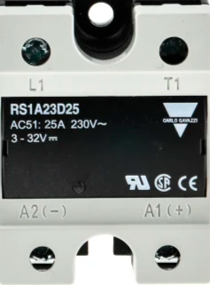
The RM1A23D25 is a solid-state relay (SSR) module manufactured by Carlo Gavazzi, with the part ID BLB042BULEBEL. This relay is designed for switching applications in electronic circuits, enabling the control of high-voltage loads using low-voltage signals. Its compact design ensures easy integration into a wide range of systems, making it a reliable choice for industrial automation, HVAC systems, lighting control, and motor control applications.
Explore Projects Built with RM1A23D25


Explore Projects Built with RM1A23D25
Common Applications
- Industrial automation systems
- Heating, ventilation, and air conditioning (HVAC) systems
- Lighting control circuits
- Motor control and protection
- Home automation and IoT devices
Technical Specifications
Key Technical Details
| Parameter | Value |
|---|---|
| Manufacturer | Carlo Gavazzi |
| Part ID | BLB042BULEBEL |
| Relay Type | Solid-State Relay (SSR) |
| Input Control Voltage | 3-32 VDC |
| Output Voltage Range | 24-280 VAC |
| Maximum Load Current | 25 A |
| Isolation Voltage | 4000 VAC |
| Switching Type | Zero-Crossing Switching |
| Operating Temperature | -30°C to +80°C |
| Mounting Type | Panel Mount |
| Dimensions | 58.2 x 44.8 x 28.8 mm |
Pin Configuration and Descriptions
The RM1A23D25 has four terminals for input and output connections. The table below describes each terminal:
| Terminal Number | Label | Description |
|---|---|---|
| 1 | + (Input) | Positive DC control signal input (3-32 VDC) |
| 2 | - (Input) | Negative DC control signal input (ground) |
| 3 | ~ (Output) | AC load terminal 1 (connected to the load) |
| 4 | ~ (Output) | AC load terminal 2 (connected to the AC source) |
Usage Instructions
How to Use the RM1A23D25 in a Circuit
- Input Control Signal: Connect a DC control signal (3-32 VDC) to the input terminals (1 and 2). Ensure the polarity is correct: terminal 1 is positive (+), and terminal 2 is negative (-).
- Load Connection: Connect the AC load to the output terminals (3 and 4). Terminal 3 is connected to one side of the load, and terminal 4 is connected to the AC power source.
- Mounting: Secure the relay to a panel or heat sink using the mounting holes provided. Proper heat dissipation is essential for reliable operation.
- Power On: Apply the control signal to the input terminals. The relay will switch the AC load on or off based on the presence of the control signal.
Important Considerations and Best Practices
- Heat Dissipation: Ensure adequate ventilation or use a heat sink to prevent overheating during operation.
- Load Ratings: Do not exceed the maximum load current (25 A) or voltage (280 VAC) to avoid damage.
- Isolation: The relay provides 4000 VAC isolation between the input and output, ensuring safety in high-voltage applications.
- Zero-Crossing Switching: The relay switches at the zero-crossing point of the AC waveform, reducing electrical noise and extending the life of the load.
Example: Connecting RM1A23D25 to an Arduino UNO
The RM1A23D25 can be controlled using an Arduino UNO. Below is an example circuit and code to toggle the relay:
Circuit Connections
- Connect the Arduino digital pin (e.g., pin 7) to the positive input terminal (1) of the relay.
- Connect the negative input terminal (2) of the relay to the Arduino GND.
- Connect the AC load to the output terminals (3 and 4) of the relay.
Arduino Code
// Define the pin connected to the relay control input
const int relayPin = 7;

void setup() {
  // Set the relay pin as an output
  pinMode(relayPin, OUTPUT);

  // Start with the relay off
  digitalWrite(relayPin, LOW);
}

void loop() {
  // Turn the relay on
  digitalWrite(relayPin, HIGH);
  delay(5000); // Keep the relay on for 5 seconds

  // Turn the relay off
  digitalWrite(relayPin, LOW);
  delay(5000); // Keep the relay off for 5 seconds
}
Troubleshooting and FAQs
Common Issues and Solutions
Relay Not Switching
- Cause: Insufficient input control voltage.
- Solution: Ensure the input control voltage is within the specified range (3-32 VDC).
Overheating
- Cause: Excessive load current or inadequate heat dissipation.
- Solution: Verify the load current does not exceed 25 A. Use a heat sink or improve ventilation.
Load Not Turning On
- Cause: Incorrect wiring of the load or AC source.
- Solution: Double-check the connections to the output terminals (3 and 4).
Electrical Noise
- Cause: High inrush current or improper grounding.
- Solution: Use a snubber circuit or ensure proper grounding of the system.
FAQs
Q1: Can the RM1A23D25 be used with DC loads?
A1: No, the RM1A23D25 is designed for AC loads only. For DC loads, use a DC-specific solid-state relay.
Q2: What is zero-crossing switching?
A2: Zero-crossing switching means the relay switches the load on or off when the AC waveform crosses zero volts. This reduces electrical noise and minimizes wear on the load.
Q3: Is the relay polarity-sensitive on the input side?
A3: Yes, the input terminals are polarity-sensitive. Ensure the positive control signal is connected to terminal 1 (+) and the negative to terminal 2 (-).
Q4: Can I control the relay with a 3.3V microcontroller?
A4: Yes, the relay can be controlled with a 3.3V signal, as it supports an input voltage range of 3-32 VDC.