Cirkit Designer
Your all-in-one circuit design IDE
Home /
Component Documentation
How to Use 8x8 dot matrix: Examples, Pinouts, and Specs
Introduction
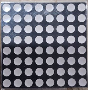
The Robotco AC072 is an 8x8 dot matrix LED display, consisting of 64 LEDs arranged in 8 rows and 8 columns. This versatile component is widely used for displaying characters, symbols, and simple graphics in various electronic devices. Its compact design and ease of integration make it a popular choice for hobbyists and professionals alike.
Explore Projects Built with 8x8 dot matrix
ESP8266 NodeMCU Controlled 8x8 LED Matrix Display
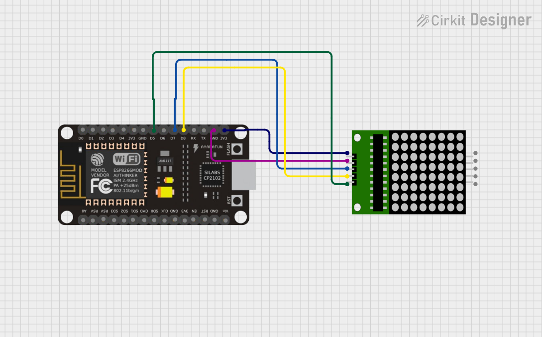
This circuit connects an ESP8266 NodeMCU microcontroller to an 8x8 LED matrix display. The NodeMCU controls the matrix using digital pins D5, D7, and D8 for chip select (CS), data input (DIN), and clock (CLK) signals, respectively. The circuit is designed to display patterns or characters on the LED matrix, which are driven by the microcontroller.
Arduino UNO-Based Interactive LED Game with 8x8 Matrix and TM1637 Display

This circuit is a game system controlled by an Arduino UNO, featuring an 8x8 LED matrix, a 4x4 keypad, and a TM1637 4-digit display. The user interacts with the game via the keypad, and the game state is displayed on the LED matrix and the TM1637 display, with power supplied by a 9V battery.
Arduino UNO Controlled LED Matrix and LCD Interface with Joystick Interaction

This circuit features an Arduino UNO microcontroller interfaced with an 8x8 LED matrix, an LCD screen, and a KY-023 Dual Axis Joystick Module. The Arduino controls the LED matrix via digital pins D10-D12 and powers the matrix, LCD, and joystick module from its 5V output. The joystick's analog outputs are connected to the Arduino's analog inputs A0 and A1 for position sensing, while the LCD is controlled through digital pins D2-D6 and D13 for display purposes.
Arduino UNO Controlled LED Matrix Display with Interactive Pushbuttons
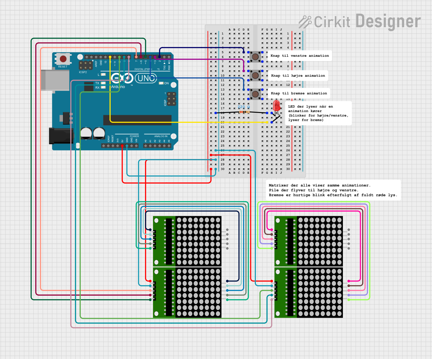
This circuit features an Arduino UNO microcontroller connected to multiple 8x8 LED matrix displays and pushbuttons. The pushbuttons are interfaced with digital pins D2, D3, and D4 on the Arduino for input, while the LED matrices are connected to digital pins D5 through D10 for control signals. Additionally, there is a single red LED with a series resistor connected to pin D12, likely used as an indicator light.
Explore Projects Built with 8x8 dot matrix
ESP8266 NodeMCU Controlled 8x8 LED Matrix Display
This circuit connects an ESP8266 NodeMCU microcontroller to an 8x8 LED matrix display. The NodeMCU controls the matrix using digital pins D5, D7, and D8 for chip select (CS), data input (DIN), and clock (CLK) signals, respectively. The circuit is designed to display patterns or characters on the LED matrix, which are driven by the microcontroller.
Arduino UNO-Based Interactive LED Game with 8x8 Matrix and TM1637 Display
This circuit is a game system controlled by an Arduino UNO, featuring an 8x8 LED matrix, a 4x4 keypad, and a TM1637 4-digit display. The user interacts with the game via the keypad, and the game state is displayed on the LED matrix and the TM1637 display, with power supplied by a 9V battery.
Arduino UNO Controlled LED Matrix and LCD Interface with Joystick Interaction
This circuit features an Arduino UNO microcontroller interfaced with an 8x8 LED matrix, an LCD screen, and a KY-023 Dual Axis Joystick Module. The Arduino controls the LED matrix via digital pins D10-D12 and powers the matrix, LCD, and joystick module from its 5V output. The joystick's analog outputs are connected to the Arduino's analog inputs A0 and A1 for position sensing, while the LCD is controlled through digital pins D2-D6 and D13 for display purposes.
Arduino UNO Controlled LED Matrix Display with Interactive Pushbuttons
This circuit features an Arduino UNO microcontroller connected to multiple 8x8 LED matrix displays and pushbuttons. The pushbuttons are interfaced with digital pins D2, D3, and D4 on the Arduino for input, while the LED matrices are connected to digital pins D5 through D10 for control signals. Additionally, there is a single red LED with a series resistor connected to pin D12, likely used as an indicator light.
Common Applications and Use Cases
- Digital Clocks: Displaying time in a visually appealing manner.
- Scrolling Text Displays: Showing messages or notifications.
- Simple Graphics: Creating basic animations or icons.
- Status Indicators: Indicating system status or alerts.
- Educational Projects: Teaching the basics of electronics and programming.
Technical Specifications
Key Technical Details
| Parameter | Value |
|---|---|
| Operating Voltage | 3.3V - 5V |
| Current per LED | 10mA (typical) |
| Power Consumption | 320mW (typical) |
| LED Color | Red |
| Dimensions | 32mm x 32mm x 8mm |
| Manufacturer | Robotco |
| Part ID | AC072 |
Pin Configuration and Descriptions
| Pin Number | Pin Name | Description |
|---|---|---|
| 1 | R1 | Row 1 Control |
| 2 | R2 | Row 2 Control |
| 3 | R3 | Row 3 Control |
| 4 | R4 | Row 4 Control |
| 5 | R5 | Row 5 Control |
| 6 | R6 | Row 6 Control |
| 7 | R7 | Row 7 Control |
| 8 | R8 | Row 8 Control |
| 9 | C1 | Column 1 Control |
| 10 | C2 | Column 2 Control |
| 11 | C3 | Column 3 Control |
| 12 | C4 | Column 4 Control |
| 13 | C5 | Column 5 Control |
| 14 | C6 | Column 6 Control |
| 15 | C7 | Column 7 Control |
| 16 | C8 | Column 8 Control |
Usage Instructions
How to Use the Component in a Circuit
- Power Supply: Connect the VCC pin to a 3.3V or 5V power supply and the GND pin to the ground.
- Row and Column Control: Use microcontroller GPIO pins to control the rows and columns. Each row and column pin corresponds to a specific LED in the matrix.
- Current Limiting Resistors: Use appropriate current limiting resistors to prevent damage to the LEDs. Typically, a 220Ω resistor is used for each row or column.
- Multiplexing: To display characters or graphics, use multiplexing techniques to control which LEDs are lit at any given time.
Important Considerations and Best Practices
- Current Limiting: Always use current limiting resistors to protect the LEDs from excessive current.
- Heat Dissipation: Ensure proper ventilation to prevent overheating, especially when multiple LEDs are lit simultaneously.
- Code Optimization: Optimize your code to minimize flickering and ensure smooth display transitions.
Example Code for Arduino UNO
// Include the necessary libraries
#include <LedControl.h>

// Define the pin connections
const int DIN_PIN = 12;  // Data In
const int CS_PIN = 11;   // Chip Select
const int CLK_PIN = 10;  // Clock

// Create an instance of the LedControl library
LedControl lc = LedControl(DIN_PIN, CLK_PIN, CS_PIN, 1);

void setup() {
  // Initialize the LED matrix
  lc.shutdown(0, false);       // Wake up the display
  lc.setIntensity(0, 8);       // Set brightness level (0-15)
  lc.clearDisplay(0);          // Clear the display
}

void loop() {
  // Display a simple pattern
  lc.setRow(0, 0, B10101010);  // Set row 0
  lc.setRow(0, 1, B01010101);  // Set row 1
  lc.setRow(0, 2, B10101010);  // Set row 2
  lc.setRow(0, 3, B01010101);  // Set row 3
  lc.setRow(0, 4, B10101010);  // Set row 4
  lc.setRow(0, 5, B01010101);  // Set row 5
  lc.setRow(0, 6, B10101010);  // Set row 6
  lc.setRow(0, 7, B01010101);  // Set row 7
  delay(1000);                 // Wait for 1 second

  // Clear the display
  lc.clearDisplay(0);
  delay(1000);                 // Wait for 1 second
}
Troubleshooting and FAQs
Common Issues Users Might Face
LEDs Not Lighting Up:
- Solution: Check the power supply connections and ensure the correct voltage is applied. Verify that the current limiting resistors are properly connected.
Flickering Display:
- Solution: Optimize the multiplexing code to reduce flickering. Ensure that the refresh rate is high enough to maintain a stable display.
Dim LEDs:
- Solution: Check the current limiting resistors and ensure they are of the correct value. Verify that the power supply can provide sufficient current.
Overheating:
- Solution: Ensure proper ventilation and avoid lighting up too many LEDs simultaneously. Use heat sinks if necessary.
Solutions and Tips for Troubleshooting
- Double-Check Connections: Ensure all connections are secure and correctly wired according to the pin configuration.
- Use a Multimeter: Measure the voltage and current at various points in the circuit to identify any discrepancies.
- Consult the Datasheet: Refer to the manufacturer's datasheet for detailed technical information and guidelines.
By following this documentation, users can effectively integrate the Robotco AC072 8x8 dot matrix into their projects, ensuring optimal performance and reliability.