Cirkit Designer Logo
Cirkit Designer
Your all-in-one circuit design IDE
Home / 
Component Documentation

How to Use esp32: Examples, Pinouts, and Specs

Image of esp32
Cirkit Designer LogoDesign with esp32 in Cirkit Designer

Introduction

The ESP32, manufactured by Espressif Systems, is a low-cost, low-power system on a chip (SoC) with integrated Wi-Fi and Bluetooth capabilities. It is widely used in Internet of Things (IoT) applications, embedded systems, and smart devices. The ESP32 Dev Module is a development board that simplifies prototyping and development with the ESP32 chip.

Explore Projects Built with esp32

Use Cirkit Designer to design, explore, and prototype these projects online. Some projects support real-time simulation. Click "Open Project" to start designing instantly!
ESP32-Controlled OLED Display and Servo with DotStar LED Strip and Audio Output
Image of Arena 2: A project utilizing esp32 in a practical application
This circuit features an ESP32 microcontroller driving a variety of components. It controls an OLED display for visual output, a DotStar LED strip for lighting effects, a PAM8403 audio amplifier connected to a speaker for sound output, and a PCA9685 PWM Servo Breakout to manage a servo motor. The ESP32 also interfaces with a piezo speaker for additional sound generation, and the circuit is powered by a 18650 Li-ion battery setup with a TP4056 charging module. The ESP32's embedded code handles the display animation on the OLED.
Cirkit Designer LogoOpen Project in Cirkit Designer
ESP32-Based Sensor Monitoring System with OLED Display and E-Stop
Image of MVP_design: A project utilizing esp32 in a practical application
This circuit features an ESP32 microcontroller that interfaces with a variety of sensors and output devices. It is powered by a Lipo battery through a buck converter, ensuring a stable voltage supply. The ESP32 collects data from a DHT11 temperature and humidity sensor and a vibration sensor, controls a buzzer, and displays information on an OLED screen. An emergency stop (E Stop) is connected for safety purposes, allowing the system to be quickly deactivated.
Cirkit Designer LogoOpen Project in Cirkit Designer
ESP32-Based Environmental Monitoring System with Motion Detection
Image of pro: A project utilizing esp32 in a practical application
This circuit features an ESP32 microcontroller on a baseboard that interfaces with a PIR sensor for motion detection, a DHT22 sensor for measuring temperature and humidity, and a BH1750 sensor for detecting ambient light levels. The ESP32 is configured to communicate with the BH1750 using I2C protocol, with GPIO22 and GPIO21 serving as the SCL and SDA lines, respectively. Power is supplied to the sensors from the ESP32's voltage output pins, and sensor outputs are connected to designated GPIO pins for data acquisition.
Cirkit Designer LogoOpen Project in Cirkit Designer
ESP32-Based Smart Weather Station with Wi-Fi Connectivity
Image of flowchart 3D: A project utilizing esp32 in a practical application
This circuit features an ESP32 microcontroller interfacing with various sensors and modules, including a DHT22 temperature and humidity sensor, an ESP32 CAM for image capture, an I2C LCD screen for display, a load cell with an HX711 interface for weight measurement, and a buzzer for audio alerts. The ESP32 handles data acquisition, processing, and communication with these peripherals to create a multi-functional monitoring and alert system.
Cirkit Designer LogoOpen Project in Cirkit Designer

Explore Projects Built with esp32

Use Cirkit Designer to design, explore, and prototype these projects online. Some projects support real-time simulation. Click "Open Project" to start designing instantly!
Image of Arena 2: A project utilizing esp32 in a practical application
ESP32-Controlled OLED Display and Servo with DotStar LED Strip and Audio Output
This circuit features an ESP32 microcontroller driving a variety of components. It controls an OLED display for visual output, a DotStar LED strip for lighting effects, a PAM8403 audio amplifier connected to a speaker for sound output, and a PCA9685 PWM Servo Breakout to manage a servo motor. The ESP32 also interfaces with a piezo speaker for additional sound generation, and the circuit is powered by a 18650 Li-ion battery setup with a TP4056 charging module. The ESP32's embedded code handles the display animation on the OLED.
Cirkit Designer LogoOpen Project in Cirkit Designer
Image of MVP_design: A project utilizing esp32 in a practical application
ESP32-Based Sensor Monitoring System with OLED Display and E-Stop
This circuit features an ESP32 microcontroller that interfaces with a variety of sensors and output devices. It is powered by a Lipo battery through a buck converter, ensuring a stable voltage supply. The ESP32 collects data from a DHT11 temperature and humidity sensor and a vibration sensor, controls a buzzer, and displays information on an OLED screen. An emergency stop (E Stop) is connected for safety purposes, allowing the system to be quickly deactivated.
Cirkit Designer LogoOpen Project in Cirkit Designer
Image of pro: A project utilizing esp32 in a practical application
ESP32-Based Environmental Monitoring System with Motion Detection
This circuit features an ESP32 microcontroller on a baseboard that interfaces with a PIR sensor for motion detection, a DHT22 sensor for measuring temperature and humidity, and a BH1750 sensor for detecting ambient light levels. The ESP32 is configured to communicate with the BH1750 using I2C protocol, with GPIO22 and GPIO21 serving as the SCL and SDA lines, respectively. Power is supplied to the sensors from the ESP32's voltage output pins, and sensor outputs are connected to designated GPIO pins for data acquisition.
Cirkit Designer LogoOpen Project in Cirkit Designer
Image of flowchart 3D: A project utilizing esp32 in a practical application
ESP32-Based Smart Weather Station with Wi-Fi Connectivity
This circuit features an ESP32 microcontroller interfacing with various sensors and modules, including a DHT22 temperature and humidity sensor, an ESP32 CAM for image capture, an I2C LCD screen for display, a load cell with an HX711 interface for weight measurement, and a buzzer for audio alerts. The ESP32 handles data acquisition, processing, and communication with these peripherals to create a multi-functional monitoring and alert system.
Cirkit Designer LogoOpen Project in Cirkit Designer

Common Applications and Use Cases

  • IoT devices and smart home automation
  • Wireless sensor networks
  • Wearable electronics
  • Industrial automation
  • Robotics and drones
  • Audio streaming and Bluetooth applications

Technical Specifications

Key Technical Details

  • Manufacturer: Espressif Systems
  • Part ID: ESP32 Dev Module
  • Processor: Dual-core Xtensa® 32-bit LX6 microprocessor
  • Clock Speed: Up to 240 MHz
  • Flash Memory: 4 MB (varies by module)
  • SRAM: 520 KB
  • Connectivity: Wi-Fi (802.11 b/g/n), Bluetooth 4.2 (Classic and BLE)
  • Operating Voltage: 3.3V
  • I/O Voltage: 3.3V (not 5V tolerant)
  • GPIO Pins: 34 (multiplexed for various functions)
  • ADC Channels: 18 (12-bit resolution)
  • DAC Channels: 2 (8-bit resolution)
  • PWM Channels: 16
  • Communication Protocols: UART, SPI, I2C, I2S, CAN, Ethernet MAC
  • Power Consumption: Ultra-low power modes available (as low as 5 µA in deep sleep)
  • Operating Temperature: -40°C to +85°C

Pin Configuration and Descriptions

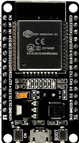
The ESP32 Dev Module has a variety of pins for different functionalities. Below is a summary of the key pins:

Pin Name Function Description
GPIO0 Input/Output, Boot Mode Select Used for boot mode selection during startup.
GPIO2 Input/Output, ADC, DAC General-purpose pin, can also function as ADC or DAC.
GPIO12 Input/Output, ADC General-purpose pin, supports ADC functionality.
GPIO13 Input/Output, ADC, Touch Sensor General-purpose pin, supports ADC and touch sensing.
GPIO15 Input/Output, ADC, PWM General-purpose pin, supports ADC and PWM.
EN Enable Active-high pin to enable or reset the chip.
3V3 Power 3.3V power supply input/output.
GND Ground Ground connection.
TX0 (GPIO1) UART Transmit UART0 transmit pin for serial communication.
RX0 (GPIO3) UART Receive UART0 receive pin for serial communication.

Note: Some GPIO pins are reserved for internal functions or have specific boot mode requirements. Refer to the ESP32 datasheet for detailed pin behavior.

Usage Instructions

How to Use the ESP32 in a Circuit

  1. Powering the ESP32:

    • Provide a stable 3.3V power supply to the 3V3 pin.
    • Connect the GND pin to the ground of your circuit.
    • Avoid applying 5V directly to any GPIO pin, as the ESP32 operates at 3.3V logic levels.
  2. Programming the ESP32:

    • Use a USB-to-serial adapter (built into most ESP32 Dev Modules) to connect the board to your computer.
    • Install the ESP32 board package in the Arduino IDE or use the Espressif IDF (IoT Development Framework) for advanced development.
  3. Connecting Peripherals:

    • Use GPIO pins for digital input/output, ADC for analog input, and DAC for analog output.
    • Connect sensors, actuators, or other devices to the appropriate pins, ensuring voltage compatibility.
  4. Uploading Code:

    • Select the correct board and COM port in the Arduino IDE.
    • Write or load your code, then click the upload button.
    • Press the EN (enable) button on the ESP32 board if required to reset the chip.

Example Code for Arduino IDE

Below is an example of how to blink an LED connected to GPIO2:

// Define the GPIO pin for the LED
#define LED_PIN 2

void setup() {
  // Set the LED pin as an output
  pinMode(LED_PIN, OUTPUT);
}

void loop() {
  // Turn the LED on
  digitalWrite(LED_PIN, HIGH);
  delay(1000); // Wait for 1 second

  // Turn the LED off
  digitalWrite(LED_PIN, LOW);
  delay(1000); // Wait for 1 second
}

Important Considerations and Best Practices

  • Voltage Levels: Ensure all connected devices operate at 3.3V logic levels. Use level shifters if interfacing with 5V devices.
  • Boot Mode: Avoid pulling GPIO0, GPIO2, or GPIO15 to incorrect states during boot, as this may prevent the ESP32 from starting properly.
  • Power Supply: Use a stable power source to avoid unexpected resets or malfunctions.

Troubleshooting and FAQs

Common Issues and Solutions

  1. ESP32 Not Detected by Computer:

    • Ensure the USB cable is functional and supports data transfer.
    • Install the correct USB-to-serial driver for your operating system.
  2. Code Upload Fails:

    • Check the selected board and COM port in the Arduino IDE.
    • Press and hold the BOOT button on the ESP32 while uploading the code.
  3. Wi-Fi Connection Issues:

    • Verify the SSID and password in your code.
    • Ensure the Wi-Fi network is within range and not using unsupported security protocols.
  4. Random Resets or Instability:

    • Check the power supply for voltage drops or noise.
    • Avoid using GPIO pins reserved for internal functions.

FAQs

Q: Can the ESP32 operate on 5V?
A: No, the ESP32 operates at 3.3V. Applying 5V to GPIO pins can damage the chip.

Q: How do I put the ESP32 into deep sleep mode?
A: Use the esp_deep_sleep_start() function in your code. Refer to the Espressif documentation for detailed instructions.

Q: Can I use the ESP32 with Bluetooth and Wi-Fi simultaneously?
A: Yes, the ESP32 supports simultaneous use of Bluetooth and Wi-Fi, but performance may vary depending on the application.

Q: What is the maximum range of the ESP32's Wi-Fi?
A: The range depends on environmental factors but typically extends up to 100 meters in open spaces.

This concludes the documentation for the ESP32 Dev Module. For more advanced features and examples, refer to the official Espressif documentation.