How to Use BMM150: Examples, Pinouts, and Specs
Introduction
The BMM150 is a 3-axis digital magnetometer designed for precise measurement of magnetic fields. It is a highly sensitive and low-power device, making it ideal for applications in navigation, orientation, and motion sensing. The BMM150 is commonly used in smartphones, wearable devices, drones, and other systems requiring accurate geomagnetic data.
Explore Projects Built with BMM150


Explore Projects Built with BMM150
Common Applications:
- Electronic compasses for navigation
- Motion tracking in augmented reality (AR) and virtual reality (VR) devices
- Orientation detection in drones and robotics
- Magnetic field mapping and measurement
- Wearable fitness devices for activity tracking
Technical Specifications
The BMM150 offers a range of features and specifications that make it suitable for a variety of applications. Below are the key technical details:
Key Specifications:
| Parameter | Value |
|---|---|
| Operating Voltage | 1.8V to 3.6V |
| Power Consumption | 170 µA (typical, normal mode) |
| Measurement Range | ±1300 µT (X, Y axes) |
| ±2500 µT (Z axis) | |
| Output Data Rate (ODR) | 10 Hz to 100 Hz |
| Communication Interface | I²C and SPI |
| Operating Temperature | -40°C to +85°C |
| Sensitivity | 0.3 µT/LSB |
| Package Type | LGA-12 (2.0 mm x 2.0 mm) |
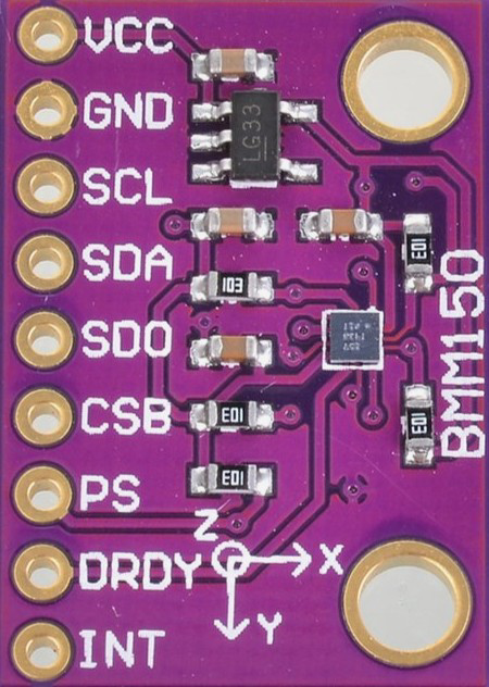
Pin Configuration:
The BMM150 comes in a 12-pin LGA package. Below is the pin configuration:
| Pin Number | Pin Name | Description |
|---|---|---|
| 1 | GND | Ground |
| 2 | VDD | Supply Voltage (1.8V to 3.6V) |
| 3 | VDDIO | I/O Voltage Supply |
| 4 | SCL | I²C Clock Line / SPI Clock (SCK) |
| 5 | SDA | I²C Data Line / SPI Data Input (SDI) |
| 6 | CSB | Chip Select (Active Low, SPI Mode Only) |
| 7 | DRDY | Data Ready Interrupt Output |
| 8 | INT | Interrupt Output |
| 9 | NC | Not Connected |
| 10 | NC | Not Connected |
| 11 | NC | Not Connected |
| 12 | GND | Ground |
Usage Instructions
The BMM150 can be easily integrated into a circuit using either the I²C or SPI communication protocol. Below are the steps and considerations for using the BMM150:
Circuit Connection:
- Power Supply: Connect the VDD pin to a 1.8V to 3.6V power source and the VDDIO pin to the desired I/O voltage level.
- Communication Interface:
- For I²C: Connect the SCL and SDA pins to the corresponding I²C lines of the microcontroller. Use pull-up resistors (typically 4.7 kΩ) on both lines.
- For SPI: Connect the SCL (SCK), SDA (SDI), and CSB pins to the corresponding SPI lines of the microcontroller.
- Interrupts: Optionally, connect the DRDY or INT pin to a GPIO pin on the microcontroller for interrupt-based data reading.
- Ground: Connect all GND pins to the ground of the circuit.
Best Practices:
- Use decoupling capacitors (e.g., 0.1 µF) near the VDD and VDDIO pins to reduce noise.
- Ensure proper PCB layout to minimize magnetic interference from other components.
- Calibrate the magnetometer in the final application to account for hard and soft iron distortions.
Example Code for Arduino UNO (I²C Mode):
Below is an example of how to interface the BMM150 with an Arduino UNO using the I²C protocol:
#include <Wire.h>

// BMM150 I2C address
#define BMM150_I2C_ADDR 0x10

// Register addresses
#define BMM150_CHIP_ID_REG 0x40
#define BMM150_DATA_X_LSB  0x42
#define BMM150_DATA_X_MSB  0x43
#define BMM150_DATA_Y_LSB  0x44
#define BMM150_DATA_Y_MSB  0x45
#define BMM150_DATA_Z_LSB  0x46
#define BMM150_DATA_Z_MSB  0x47

void setup() {
  Wire.begin(); // Initialize I2C communication
  Serial.begin(9600); // Initialize serial communication for debugging

  // Check BMM150 chip ID
  Wire.beginTransmission(BMM150_I2C_ADDR);
  Wire.write(BMM150_CHIP_ID_REG);
  Wire.endTransmission();
  Wire.requestFrom(BMM150_I2C_ADDR, 1);

  if (Wire.available()) {
    uint8_t chipID = Wire.read();
    if (chipID == 0x32) { // Expected chip ID for BMM150
      Serial.println("BMM150 detected!");
    } else {
      Serial.println("BMM150 not detected. Check connections.");
    }
  }
}

void loop() {
  int16_t magX, magY, magZ;

  // Read X-axis data
  magX = readAxisData(BMM150_DATA_X_LSB, BMM150_DATA_X_MSB);
  // Read Y-axis data
  magY = readAxisData(BMM150_DATA_Y_LSB, BMM150_DATA_Y_MSB);
  // Read Z-axis data
  magZ = readAxisData(BMM150_DATA_Z_LSB, BMM150_DATA_Z_MSB);

  // Print magnetic field data
  Serial.print("X: ");
  Serial.print(magX);
  Serial.print(" µT, Y: ");
  Serial.print(magY);
  Serial.print(" µT, Z: ");
  Serial.print(magZ);
  Serial.println(" µT");

  delay(500); // Delay for readability
}

int16_t readAxisData(uint8_t lsbReg, uint8_t msbReg) {
  uint8_t lsb, msb;

  // Read LSB
  Wire.beginTransmission(BMM150_I2C_ADDR);
  Wire.write(lsbReg);
  Wire.endTransmission();
  Wire.requestFrom(BMM150_I2C_ADDR, 1);
  lsb = Wire.available() ? Wire.read() : 0;

  // Read MSB
  Wire.beginTransmission(BMM150_I2C_ADDR);
  Wire.write(msbReg);
  Wire.endTransmission();
  Wire.requestFrom(BMM150_I2C_ADDR, 1);
  msb = Wire.available() ? Wire.read() : 0;

  // Combine MSB and LSB
  return (int16_t)((msb << 8) | lsb);
}
Notes:
- The example code assumes the BMM150 is connected to the default I²C address (0x10).
- Ensure the Arduino UNO's I²C pins (A4 for SDA, A5 for SCL) are connected to the BMM150.
Troubleshooting and FAQs
Common Issues:
BMM150 Not Detected:
- Ensure the I²C address (0x10) is correct.
- Check the wiring and ensure pull-up resistors are used on the I²C lines.
- Verify the power supply voltage is within the specified range.
Incorrect Magnetic Field Readings:
- Perform calibration to account for environmental magnetic interference.
- Ensure the BMM150 is placed away from ferromagnetic materials.
No Data Output:
- Check if the DRDY pin is signaling data availability.
- Verify the communication protocol (I²C or SPI) is correctly configured.
FAQs:
Q: Can the BMM150 be used for 3D orientation?
A: Yes, the BMM150 can be combined with an accelerometer and gyroscope to provide 3D orientation data.
Q: What is the maximum sampling rate of the BMM150?
A: The BMM150 supports an output data rate (ODR) of up to 100 Hz.
Q: How do I calibrate the BMM150?
A: Calibration involves collecting data while rotating the sensor in all directions and applying algorithms to correct for hard and soft iron distortions.