How to Use esp8266: Examples, Pinouts, and Specs
Introduction
The ESP8266 is a low-cost Wi-Fi microchip with a full TCP/IP stack and microcontroller capability, making it a popular choice for Internet of Things (IoT) applications. It allows devices to connect to Wi-Fi networks and communicate over the internet, enabling smart home devices, wireless sensors, and other connected systems.
Explore Projects Built with esp8266


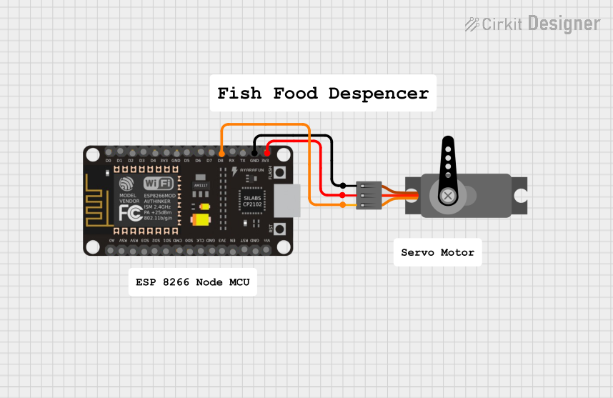
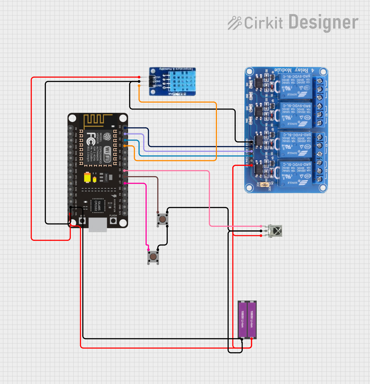
Explore Projects Built with esp8266
Common Applications and Use Cases
- Home automation systems
- Wireless sensor networks
- IoT devices and prototypes
- Smart appliances
- Remote data logging and monitoring
- Wi-Fi-enabled robotics
Technical Specifications
The ESP8266 is available in various module formats, with the ESP-01 being one of the most common. Below are the key technical details and pin configurations for the ESP-01 module.
Key Technical Details
| Parameter | Value |
|---|---|
| Microcontroller | Tensilica L106 32-bit RISC |
| Operating Voltage | 3.0V - 3.6V |
| Flash Memory | 512 KB to 4 MB (varies by model) |
| Clock Speed | 80 MHz (up to 160 MHz) |
| Wi-Fi Standards | 802.11 b/g/n |
| Wi-Fi Security | WPA/WPA2 |
| GPIO Pins | 2 (on ESP-01) |
| Communication Protocols | UART, SPI, I2C |
| Power Consumption | 15 µA (deep sleep), ~70 mA (active) |
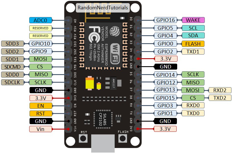
Pin Configuration and Descriptions
ESP-01 Module Pinout
| Pin Name | Pin Number | Description |
|---|---|---|
| VCC | 1 | Power input (3.3V). Do not exceed 3.6V. |
| GND | 2 | Ground connection. |
| TX | 3 | UART Transmit pin. Used for serial communication. |
| RX | 4 | UART Receive pin. Used for serial communication. |
| CH_PD | 5 | Chip enable. Must be connected to 3.3V to enable the chip. |
| GPIO0 | 6 | General-purpose I/O pin. Used for boot mode selection. |
| GPIO2 | 7 | General-purpose I/O pin. |
| RST | 8 | Reset pin. Pull low to reset the module. |
Usage Instructions
How to Use the ESP8266 in a Circuit
- Power Supply: Ensure the ESP8266 is powered with a stable 3.3V source. Using higher voltages can damage the module.
- Connections:
- Connect the
VCCpin to a 3.3V power source. - Connect the
GNDpin to the ground of your circuit. - Use a voltage divider or level shifter for the
RXpin if connecting to a 5V microcontroller. - Pull the
CH_PDpin high (to 3.3V) to enable the module.
- Connect the
- Serial Communication: Use the
TXandRXpins to communicate with a microcontroller or USB-to-serial adapter.
Important Considerations and Best Practices
- Voltage Levels: The ESP8266 operates at 3.3V. Ensure all GPIO pins and the power supply are within this range.
- Boot Modes: The module's boot mode is determined by the state of
GPIO0andGPIO2during power-up:- Normal operation:
GPIO0andGPIO2pulled high. - Flash mode:
GPIO0pulled low andGPIO2pulled high.
- Normal operation:
- Antenna Placement: For optimal Wi-Fi performance, ensure the module's antenna is not obstructed by metal or other materials.
Example: Connecting ESP8266 to Arduino UNO
Below is an example of how to connect the ESP8266 to an Arduino UNO and send data to a Wi-Fi network.
Circuit Connections
| ESP8266 Pin | Arduino UNO Pin |
|---|---|
| VCC | 3.3V |
| GND | GND |
| TX | Pin 10 |
| RX | Pin 11 (via voltage divider) |
| CH_PD | 3.3V |
Arduino Code Example
#include <SoftwareSerial.h>

// Define RX and TX pins for SoftwareSerial
SoftwareSerial esp8266(10, 11); // RX, TX

void setup() {
  // Start serial communication with the ESP8266
  Serial.begin(9600); // For debugging
  esp8266.begin(9600); // Communication with ESP8266

  // Send AT command to test communication
  Serial.println("Sending AT command to ESP8266...");
  esp8266.println("AT");
}

void loop() {
  // Check if the ESP8266 has sent any data
  if (esp8266.available()) {
    String response = esp8266.readString();
    Serial.println("ESP8266 Response: " + response);
  }

  // Check if the user has sent any data via Serial Monitor
  if (Serial.available()) {
    String command = Serial.readString();
    esp8266.println(command); // Send command to ESP8266
  }
}
Notes:
- Use a voltage divider on the
RXpin to step down the Arduino's 5V signal to 3.3V. - Ensure the ESP8266 is in normal operation mode (both
GPIO0andGPIO2pulled high).
Troubleshooting and FAQs
Common Issues and Solutions
ESP8266 Not Responding to AT Commands:
- Ensure the
CH_PDpin is connected to 3.3V. - Verify the baud rate. Some modules use 115200 by default instead of 9600.
- Check the power supply. The ESP8266 requires a stable 3.3V source.
- Ensure the
Wi-Fi Connection Fails:
- Double-check the SSID and password in your code.
- Ensure the Wi-Fi network is within range and not using unsupported security protocols.
Module Overheating:
- Verify that the power supply is not exceeding 3.6V.
- Avoid prolonged high-current operations without proper heat dissipation.
Random Resets or Instability:
- Use a capacitor (e.g., 10 µF) across the
VCCandGNDpins to stabilize the power supply. - Check for loose connections or poor soldering.
- Use a capacitor (e.g., 10 µF) across the
FAQs
Q: Can the ESP8266 be programmed directly without an external microcontroller?
A: Yes, the ESP8266 has a built-in microcontroller and can be programmed using the Arduino IDE or other tools.
Q: What is the maximum range of the ESP8266 Wi-Fi module?
A: The range depends on the environment but is typically around 50 meters indoors and up to 100 meters outdoors.
Q: Can the ESP8266 operate on 5V?
A: No, the ESP8266 operates at 3.3V. Using 5V can damage the module.
Q: How do I update the firmware on the ESP8266?
A: Firmware updates can be performed using tools like the ESP Flash Download Tool and a USB-to-serial adapter. Ensure GPIO0 is pulled low during the update process.