
How to Use Pixi cam: Examples, Pinouts, and Specs
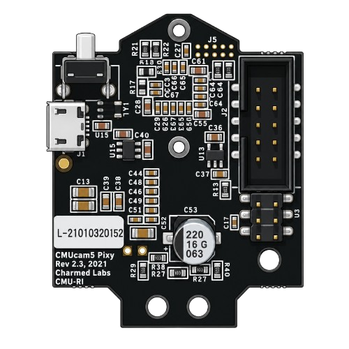
 Design with Pixi cam in Cirkit Designer
Introduction
The Pixi Cam, manufactured by Arduino (Part ID: Pixi Cam), is a compact and versatile camera module designed for robotics and computer vision applications. It is capable of capturing high-resolution images and video, making it an ideal choice for projects requiring object detection, tracking, and image processing. The Pixi Cam is optimized for integration with microcontrollers, including Arduino boards, and offers a user-friendly interface for rapid prototyping and development.
Explore Projects Built with Pixi cam
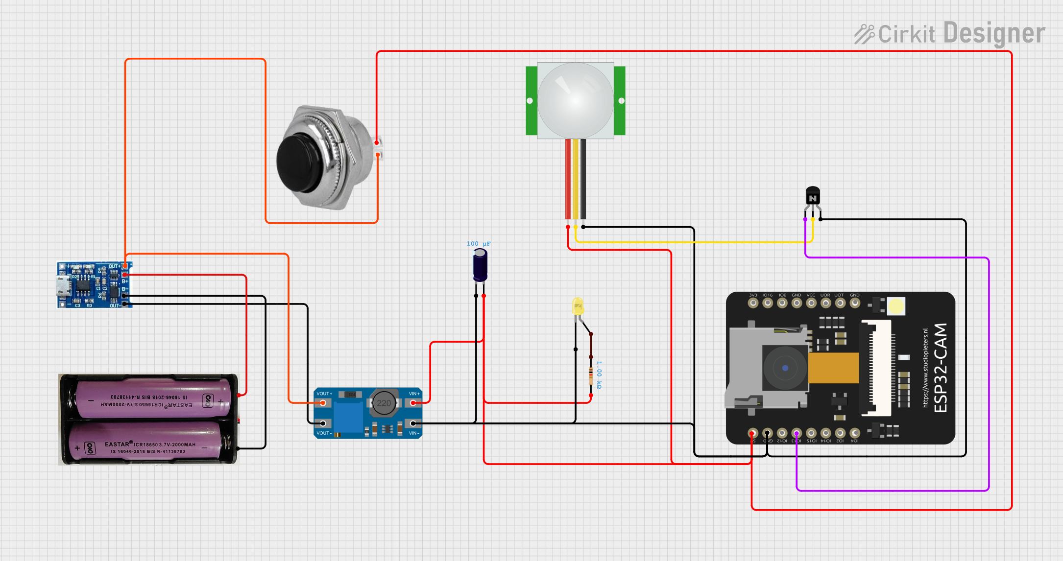 Open Project in Cirkit Designer
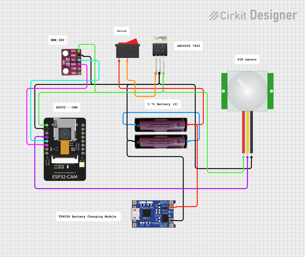 Open Project in Cirkit Designer
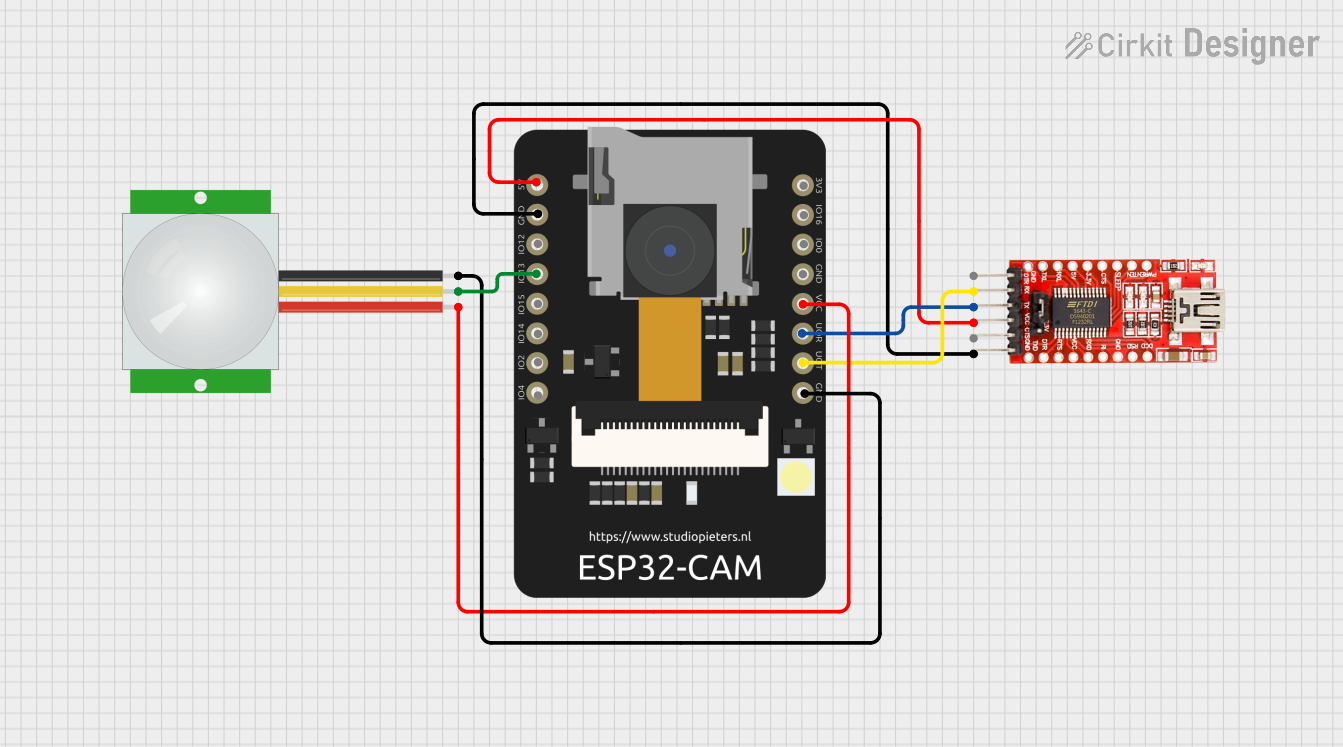 Open Project in Cirkit Designer
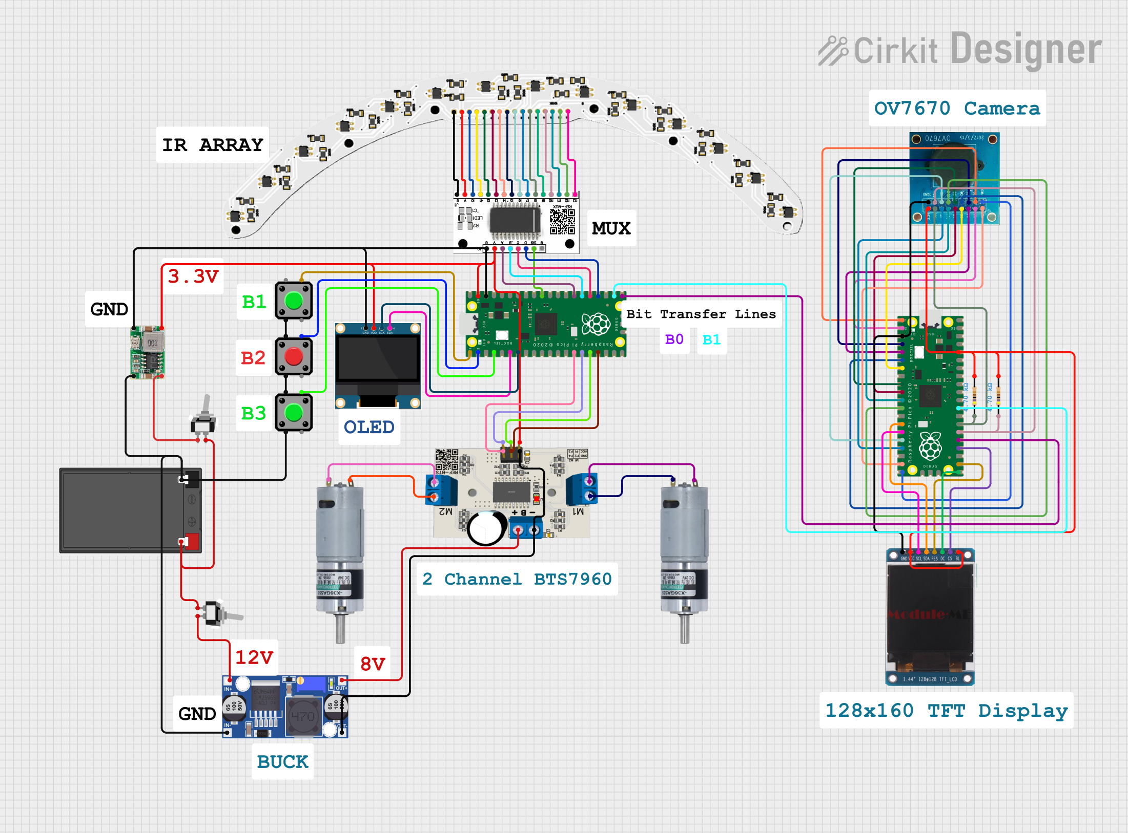 Open Project in Cirkit Designer
Explore Projects Built with Pixi cam
Open Project in Cirkit DesignerOpen Project in Cirkit DesignerOpen Project in Cirkit DesignerOpen Project in Cirkit DesignerCommon Applications
- Object detection and tracking in robotics
- Line-following robots
- Gesture recognition systems
- Surveillance and security systems
- Educational projects involving computer vision
Technical Specifications
The Pixi Cam is designed to deliver reliable performance in a variety of applications. Below are its key technical specifications:
| Specification | Details |
|---|---|
| Manufacturer | Arduino |
| Part ID | Pixi Cam |
| Image Resolution | Up to 1280 x 720 pixels (HD) |
| Frame Rate | Up to 60 frames per second (fps) |
| Communication Protocol | UART, I2C, SPI |
| Operating Voltage | 5V DC |
| Power Consumption | ~150 mA |
| Lens Type | Fixed-focus lens |
| Field of View (FOV) | 75° diagonal |
| Dimensions | 25mm x 25mm x 20mm |
| Weight | 10g |
Pin Configuration
The Pixi Cam features a simple pinout for easy integration with microcontrollers. Below is the pin configuration:
| Pin | Name | Description |
|---|---|---|
| 1 | VCC | Power supply (5V DC) |
| 2 | GND | Ground |
| 3 | TX | UART Transmit (data output) |
| 4 | RX | UART Receive (data input) |
| 5 | SDA | I2C Data Line |
| 6 | SCL | I2C Clock Line |
| 7 | CS | SPI Chip Select |
| 8 | MOSI | SPI Master Out Slave In |
| 9 | MISO | SPI Master In Slave Out |
| 10 | SCK | SPI Clock |
Usage Instructions
Connecting the Pixi Cam to an Arduino UNO
To use the Pixi Cam with an Arduino UNO, follow these steps:
- Wiring: Connect the Pixi Cam to the Arduino UNO as follows:
- VCC to 5V on the Arduino
- GND to GND on the Arduino
- TX to Digital Pin 10 (for UART communication)
- RX to Digital Pin 11 (for UART communication)
- Install Libraries: Download and install the Pixi Cam library from the Arduino IDE Library Manager.
- Upload Code: Use the example code below to test the Pixi Cam.
Example Code
The following Arduino sketch demonstrates how to initialize the Pixi Cam and read object tracking data:
#include <PixiCam.h> // Include the Pixi Cam library

PixiCam pixi; // Create a PixiCam object

void setup() {
  Serial.begin(9600); // Initialize serial communication
  pixi.begin(); // Initialize the Pixi Cam

  // Check if the Pixi Cam is connected
  if (!pixi.isConnected()) {
    Serial.println("Pixi Cam not detected. Check connections.");
    while (1); // Halt execution if the camera is not detected
  }

  Serial.println("Pixi Cam initialized successfully.");
}

void loop() {
  // Check if the Pixi Cam detects an object
  if (pixi.isObjectDetected()) {
    int x = pixi.getObjectX(); // Get the X-coordinate of the object
    int y = pixi.getObjectY(); // Get the Y-coordinate of the object
    Serial.print("Object detected at: ");
    Serial.print("X = ");
    Serial.print(x);
    Serial.print(", Y = ");
    Serial.println(y);
  } else {
    Serial.println("No object detected.");
  }

  delay(100); // Wait for 100ms before the next reading
}
Important Considerations
- Ensure the Pixi Cam is powered with a stable 5V supply to avoid performance issues.
- Use appropriate pull-up resistors for I2C communication if required.
- Avoid exposing the camera lens to direct sunlight or harsh environments to maintain image quality.
Troubleshooting and FAQs
Common Issues
Pixi Cam not detected by the Arduino:
- Verify the wiring connections, especially the TX and RX pins.
- Ensure the Pixi Cam library is correctly installed in the Arduino IDE.
- Check the power supply voltage (should be 5V DC).
No object detected:
- Ensure the object is within the camera's field of view.
- Verify that the lighting conditions are adequate for object detection.
Unstable or noisy data:
- Use shorter wires to reduce signal interference.
- Add decoupling capacitors near the power pins to stabilize the power supply.
FAQs
Q: Can the Pixi Cam be used with other microcontrollers?
A: Yes, the Pixi Cam supports UART, I2C, and SPI communication, making it compatible with a wide range of microcontrollers.
Q: What is the maximum distance for object detection?
A: The maximum detection distance depends on the size and lighting of the object but is typically up to 2 meters.
Q: Can the Pixi Cam capture video?
A: Yes, the Pixi Cam can capture video, but additional processing may be required to stream or store the video data.
Q: Is the Pixi Cam suitable for outdoor use?
A: The Pixi Cam is not weatherproof. For outdoor use, ensure it is housed in a protective enclosure.
By following this documentation, users can effectively integrate the Pixi Cam into their projects and troubleshoot common issues.